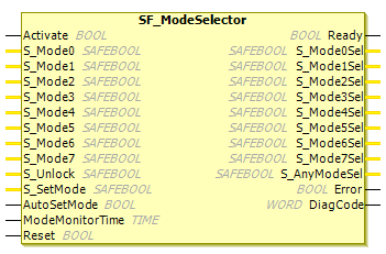
SF_ModeSelector
Tip
The version of the function block as described here corresponds to the latest version of the function block in Version list of function blocks.
Applicable safety standards
SF_ModeSelector is a certified PLCopen function block. For detailed information about applied standards, see "PLCopen – Technical Committee 5 – Safety Software".
Important
The requirements listed in the standards must be fulfilled by the user.
Interface description
This function block selects the system operation mode, such as manual, automatic, semi-automatic, etc.
Name | Data Type | Initial Value | Description, parameter values |
|---|---|---|---|
|
|
| |
|
|
| Variable or constant. Input
|
|
|
| Variable or constant. Input 0 of the mode selection switch
|
|
|
| Variable or constant. Input
|
|
|
| Variable or constant. Input
|
|
|
| Variable or constant. Input
|
|
|
| Variable or constant. Input
|
|
|
| Variable or constant. Input
|
|
|
| Variable or constant. Input
|
|
|
| Variable or constant. Locks the selected mode.
|
|
|
| Variable (or constant Sets the selected mode. Operator confirms the setting of a mode. Any change to a new |
|
|
| Constant Parameterizes the confirmation mode.
|
|
|
| Constant Maximum time allowed for changing the selection input. The |
|
|
|
ModeMonitorTime
For developers in Extended Level: The ModeMonitorTime input has to be set to a constant value. This means that the value must not be changed for the calls.
Name | Data Type | Initial Value | Description, parameter values |
|---|---|---|---|
|
|
| |
|
|
| Indicates that mode 0 is selected and confirmed.
|
|
|
| Indicates that mode 1 is selected and confirmed.
|
|
|
| Indicates that mode 2 is selected and confirmed.
|
|
|
| Indicates that mode 3 is selected and confirmed.
|
|
|
| Indicates that mode 4 is selected and confirmed.
|
|
|
| Indicates that mode 5 is selected and confirmed.
|
|
|
| Indicates that mode 6 is selected and confirmed.
|
|
|
| Indicates that mode 7 is selected and confirmed.
|
|
|
| Indicates that one of the 8 modes is selected and confirmed.
|
|
|
| |
|
|
|
Functional description
This function block block selects the system operation mode, such as manual, automatic, semi-automatic, etc. When starting the controller, it should be assumed that the machine is in a safe mode. When starting the machine, the transition to the mode set by the mode selector must be initiated by a device input (e.g. START button of the machine).
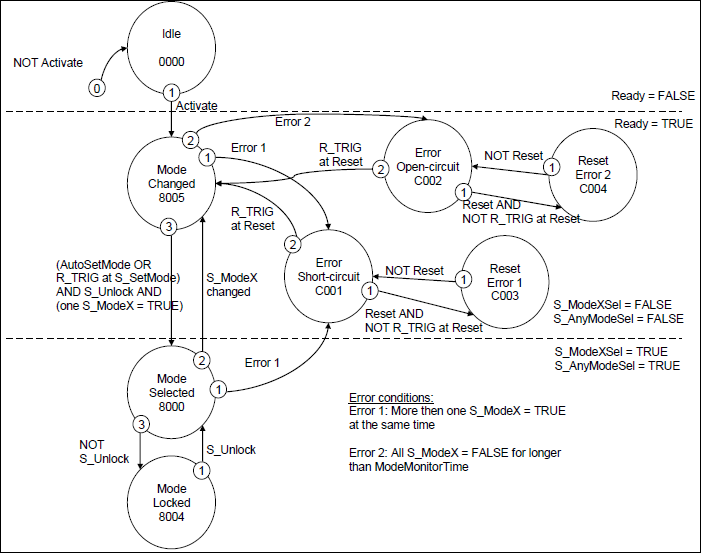
The activation of the FB following the default state is the ModeChanged state. This is also the safe state of the FB, where all S_ModeXSel and S_AnyModeSel are FALSE.
The new
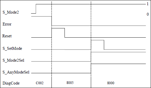
S_ModeXinput must be confirmed with a risingS_SetModetrigger edge (in caseAutoSetMode = FALSE), which leads to a newS_ModeXSeloutput.The new
S_ModeXinput automatically leads to anS_ModeXSeloutput (in caseAutoSetMode = TRUE).Such a transition from state
8005to8000is valid only if oneS_ModeXinput isTRUE. As long as allS_ModeXare FALSE, the FB remains in state8005, even ifS_SetModetriggers.
The transition from ModeChanged to ModeSelected state, that is S_SetMode is set by the operator, is not monitored by a timer.
When the FB is in the ModeSelected state, the simultaneous occurrence of a new S_ModeX input (higher priority) and the NOT S_Unlock signal (lower priority) leads to the ModeChanged state.
The S_ModeX input parameters which are not used for mode selection should be assigned the default value FALSE to simplify the verification of the program.
Caution
The AutoSetMode input should be activated only if it is guaranteed that no hazard can occur when the S-PLC is started.
Status diagram
Tip
Note: The transition from any state to the Idle state, initiated by Activate = FALSE, is not shown. In every case, these transitions have the highest priority.
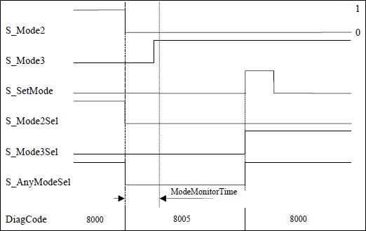
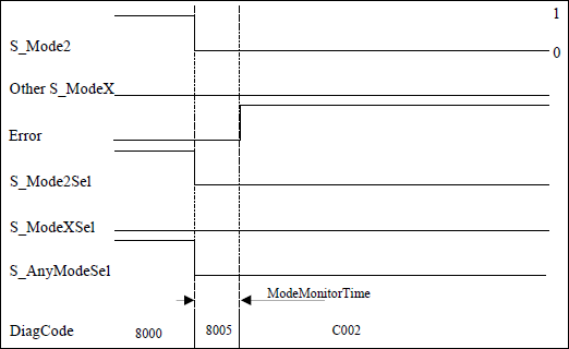
Typical timing diagrams
Error detection
ModeMonitorTime expires:Which restarts at each falling trigger edge of an
S_ModeXinputWhich is then in the
ModeChangedstate, which follows the activation of the FB.
In contrast, the FB directly detects whether or not more than one S_ModeX input is selected at the same time.
A static reset condition is detected when the FB is in either error state C001 or C002.
Error behavior
In the case of an error event, the S_ModeXSel and S_AnyModeSel outputs are set to the safe state (FALSE). The DiagCode input displays the relevant error code and the Error output is set to TRUE.
An error must be detected with the rising trigger edge of the Reset BOOL input. The FB switches from an Error state to the ModeChanged state.
FB-specific status and error codes
| Statue Name | Status description and output setting |
|---|---|---|
|
| The FB detects that two or more
All |
|
| The FB detects that all
All |
|
| Static reset signal detected in status
All |
|
| Static reset signal detected in status
All |
| Statue Name | Status description and output setting |
|---|---|---|
|
| The function block is not active (basic state).
All |
|
| Status after activation or when
All |
|
| Valid mode selection, but not yet locked.
|
|
| Valid mode selection is locked.
|