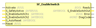
SF_EnableSwitch
Tip
The version of the function block as described here corresponds to the latest version of the function block in Version list of function blocks.
Applicable safety standards
SF_EnableSwitch is a certified PLCopen function block. For detailed information about applied standards, see "PLCopen – Technical Committee 5 – Safety Software".
Important
The requirements listed in the standards must be fulfilled by the user.
Interface description
The SF_EnableSwitch function block evaluates the signals of a manually operated, three-stage consent switch to support the cancellation of a safety measure.
Name | Data Type | Initial Value | Description, parameter values |
|---|---|---|---|
|
|
| |
|
|
| Variable or constant Confirmation of safe mode (limitation of velocity, movement energy, or movement range).
|
|
|
| Variable Signal of contacts
|
|
|
| Variable Signal of contacts
|
|
|
| |
|
|
|
Name | Data Type | Initial Value | Description, parameter values |
|---|---|---|---|
|
|
| |
|
|
| Safety-oriented output: Indicates the cancellation of the safety measure.
|
|
|
| |
|
|
|
Functional description
In accordance with the European standard, the SF_EnableSwitch function block supports the cancellation of the safety measure using enable switches when the relevant operating mode is selected and active. The corresponding operating mode (limitation of speed or movement energy, limitation of movement range) has to be selected outside this function block.
The SF_EnableSwitch function block evaluates the signals of a 3-stage enable switch.
The input parameters S_EnableSwitchCh1 and S_EnableSwitchCh2 process the following signal stages of the contacts E1 to E4.
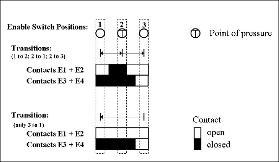
The signals of E1+E2 have to be connected with the parameter S_EnableSwitchCh1. The signals of E3+E4 have to be connected with the parameter S_EnableSwitchCh2. The position of the enable switch is detected in the function block when using the signal sequence. The transition from position 2 to position 3 can be different from what is shown here.
The switching direction (position 1 -> position 2/position 3 -> position 2) can be detected in the function block if the defined signal sequence of the enable switch contacts is used. The cancellation of the safety measure can only be activated by the function block by changing from position 1 to position 2. Other switching directions or positions must not be used to cancel the safety measure.
The user needs to use a suitable switching device as the enable switch. In addition, the user needs to ensure that the appropriate operating mode is selected in the application. (Automatic operation has to be deactivated for this operating mode, by applying appropriate measures).
The operating mode is usually defined by an operating mode selector switch in conjunction with the SF_ModeSelector FB and the SF_SafeRequest FB.
SF_EnableSwitch processes the confirmation of the "safe state" status using the S_SafetyActive parameter. When implemented in a safe application without confirmation, a static TRUE signal is associated with the S_SafetyActive parameter.
Caution
The S_AutoReset input should be activated only if it is guaranteed that no hazard can occur when the S-PLC is started.
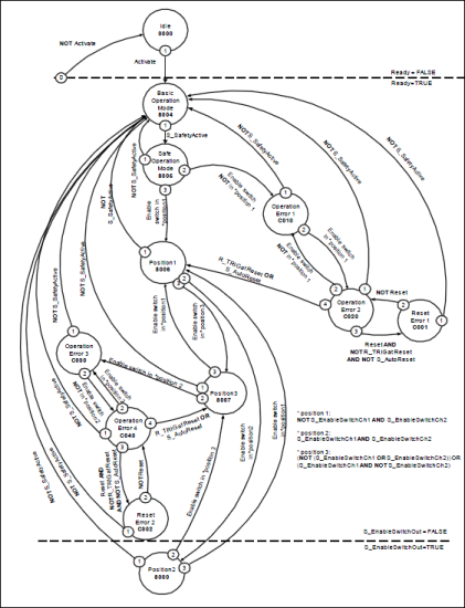
Status diagram
Tip
Note: The transition from any state to the Idle state, initiated by Activate = FALSE, is not shown. In every case, these transitions have the highest priority.
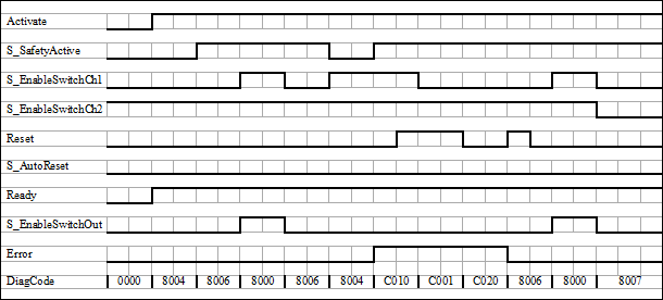
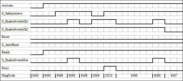
Typical timing diagrams
Error detection
The following conditions force a transition to the error status:
Invalid
Resetsignal in the processInvalid switch position
Error behavior
In case of an error event, the S_EnableSwitchOut output is set to FALSE and remains in this safe state.
Unlike other function blocks, a Reset error state can be exited by the condition Reset = FALSE, or also by S_SafetyActive = FALSE.
As soon as the error has been corrected, the enable switch has to be in the home position which is specified in the process. Only then can the S_EnableSwitchOut output be set to TRUE using the enable switch. If S_AutoReset = FALSE, then a rising trigger edge is required at Reset.
FB-Specific Error and Status Codes
| Statue Name | Status description and output setting |
|---|---|---|
|
| Static
|
|
| Static
|
|
| Enable switch is not in position
|
|
| Enable switch is in position
|
|
| Enable switch is in position
|
|
| Enable switch is not in position
|
| Statue Name | Status description and output setting |
|---|---|---|
|
| The function block is not active (basic state).
|
|
| Safe operating mode is not active.
|
|
| Safe operating mode is active.
|
|
| Safe operating mode is active and the enable switch is in position
|
|
| Safe operating mode is active and the enable switch is in position
|
|
| Safe operating mode is active and the enable switch is in position
|