CODESYS Depictor Editor (licensed)
In the licensed and paid version of the CODESYS Depictor Editor (available in the CODESYS Store), you can view and edit available Depictor objects and populate them with local variables.
Different from the CODESYS Depictor Viewer, you can also add new poses and elements to the tree and configure them in the respective property view. The 3D view shows the entire structure described in the tree.
Different from the CODESYS Depictor Viewer, the CODESYS Depictor Editor provides the following extensions:
The CODESYS main window contains an additional toolbar with command buttons for working in the CODESYS Depictor Editor.
The properties editor provides more editing options.
An interface editor is provided for Depictor objects which are located in the POUs view. Then you can reference these kinds of objects in other Depictor objects and assign the interface variables accordingly.
A Camera view is provided, where you can manage camera settings for the 3D view. These settings are accessed then by means of the IEC code.
A Lighting view is provided, where you can configure multiple light sources for lighting the 3D view.
A Bird's Eye view is provided, where you can get an overview of the scene. You see the Depictor objects, the light sources, and the camera. The camera view is always from above (in the z-axis of the scene).
You can display the parent-child relationship between poses in the form of cylinders in the 3D view.
Working in the 3D view: Poses, elements, camera positions, and pose connections
When working in the 3D view, buttons for the following commands are available in the toolbar of the CODESYS main window:
 | Add pose: A pose is added below the selected entry in the tree. Definition: A pose shows the translation of its child node relative to their parent node. For example, all child nodes should be moved seven units relative to the parent node. |
 | Add element: An element is added below the selected entry in the tree. Definition: An element in the CODESYS Depictor contains the actual 3D geometry of a Depictor object. The 3D geometry can originate from a file, or it can reference an existing Depictor object. |
 | Get camera position from render view and add it to the camera positions of Depictor. Corresponds to the command Get camera position. |
 | Set the camera position selected in Depictor to the camera position of the 3D view: Corresponds to the command Set camera position. The representation in 3D view changes accordingly. |
 | Create screenshot: The default Save as dialog opens. You can save the current 3D view to a |
 | Show pose connections: All elements are drawn as a wire model in the 3D view. The connections between the poses are displayed as green cylinders. The thickness of the cylinders is defined in the Depictor options. 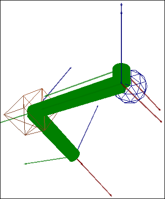 |
The commands Add pose and Add element are available in the context menu of the objects in the Tree view.
Properties view of a pose
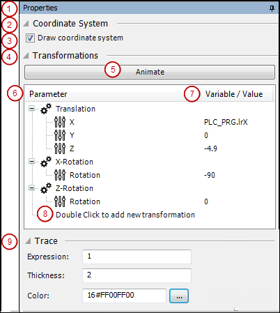
The figure shows the editor view for the Properties (1) of a pose with sample values.
Coordinate system (2), Draw coordinate system (3): When you select this option for a pose, the coordinate system for the position and transformation is displayed continuously, regardless of the selection in the tree structure.
Publish pose: This option is available for objects in the POU pool only. When the option is activated, the pose appears immediately in all elements that reference the Depictor object. You can modify the pose individually and include your own elements below it.
Button Animate (5): Animates all transformations of the pose in the defined order in the 3D view. The values defined in the Value column are incremented within one second from
0or1to the next reached value. In this way, it is easy to see how each transformation affects the model in the 3D view.Transformations (4): In the following table, you find all translations of the pose in the order of execution (top to bottom).
Parameter column (6): Transformation type with its properties
Value /Variable column (7): Value, variable, or expression that describes the respective transformation property. In offline mode, the CODESYS Depictor attempts to evaluate the expression directly and determine a value. In online mode, the expression is evaluated live. If an expression cannot be evaluated (offline or online) or it is empty, then the CODESYS Depictor attempts to use a previously determined value and finally uses
0(orFALSE).You can edit the Value /Variable column. Numeric values are permitted, in addition to variables and IEC expressions from combinations of both (example: "
q + p*2 + 5"). For expressions, you can use global IEC variables or variables from the interface of the associated Depictor object in the POU pool.In the context menu of a selected transformation, commands are available for Move Up or Move Down within the table, as well as copy or remove.
An additional transformation can be added at the end of the table: Double-click to add new transformation (8). A list box provides the possible transformation types:
Translation (X/Y/Z)
X-Rotation
Y-Rotation
Z-Rotation
Scaling (X/Y/Z)
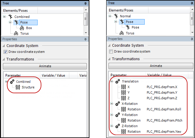
Combined (structure): Instead of using the specific X/Y/Z-parameters, translation and rotation are combined by specifying a structured variable. For this purpose, you can define a structure with the frame variables
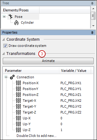
X,Y,Z,Pitch,Yaw, andRoll. As an alternative, you can use theDepictorFramestructure from theDepictorBaselibrary. See the following example for this:Connection: This transformation type is used for creating an element that is stretched in space between two points and its movements should be adapted automatically. For example, this is a robot arm that is moved in and out dynamically. For this purpose, you only have to specify the positions of both limited spatial points and a direction vector. Then the CODESYS Depictor calculates the pose for the connection element and scales it automatically. The following values are specified in the pose properties. They define its own coordinate system for the connection line inserted below the pose in the tree.
Origin position: Position X, Position Y, Position Z
Target position: Target X, Target Y, Target Z
Direction: Up X, Up Y, Up Z (Up vector)
See the following example for this:
Trace (9): These properties are used for defining whether and how the motion path of TCP is drawn.
Expression: Expression or constant (
0: no path drawn;1: draw path;2: delete path)Line width: Line width of the drawn path
Color: Color of the path drawn
DepictorFrameTYPE DepictorFrame :
STRUCT
X : LREAL;
Y : LREAL;
Z : LREAL;
Yaw : LREAL;
Pitch : LREAL;
Roll : LREAL;
END_STRUCT
END_TYPE
PROGRAM PLC_PRG
VAR
rCount : LREAL;
depFram : DepictorBase.DepictorFrame;
END_VAR
rCount := rCount + 0.01;
depFram.X := COS(rCount)*4;
depFram.Y := SIN(rCount)*4;
depFram.Z := COS(rCount) * SIN(rCount) * 4;
depFram.Yaw := rCount*4;
depFram.Pitch := rCount*8;
depFram.Roll := rCount*12;Entry in the editor: configuration table Transformations of the pose, type Combined, column Variable/Value: PLC_PRG.depFram
See the following images for the configuration of a combined transformation above the structure (left) and the equivalent configuration above the individual parameters for translation and rotation (right):
The CODESYS Depictor should display the movements of a telescopic cylinder. The movement in space and the change in the length of the cylinder should be adapted automatically to the current position of two points in space. For this purpose, you use the transformation type "Connection" for the cylinder pose and specify both spatial points and a direction vector. Then the constantly required translation for the cylinder is calculated automatically by CODESYS Depictor.
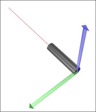
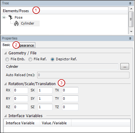
You create a "Cylinder" element below a pose in the Tree of the Depictor object (1).
The element is then a Depictor reference from a library.
Configure the Cylinder element in the Properties view (2) as follows:
In the Basic tab (2), set the transformation (3):
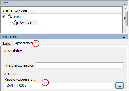
In the Appearance tab (4), set the color (5):
Then configure the pose for Cylinder in the Properties/Transformations view (3) as follows:
Control a movement of the Depictor object by means of the application program
Application, PLC_PRG
PROGRAM PLC_PRG
VAR
        lrRun : LREAL;

        lrX1 : LREAL := 0;
        lrY1 : LREAL;
        lrZ1 : LREAL;

        lrX2 : LREAL := 2;
        lrY2 : LREAL;
        lrZ2 : LREAL;

END_VAR
lrRun := lrRun + 0.01; lrX1 := COS(lrRun)*2; lrX2 := SIN(lrRun)*2 + 2; lrY1 := SIN(lrRun*2)*3; lrY2 := COS(lrRun*2)*3; lrZ1 := COS(lrRun/2); lrZ2 := SIN(lrRun/2);
Properties view of an element
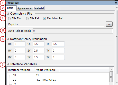
The Properties editor (1) for a Depictor element consists of the tabs Basic and Appearance. For elements that are not Depictor references, there is also the Material tab.
Basic tab (2):
Define the geometry source and set additional X/Y/Z-transformations for the element. If the element originates from a Depictor reference that defined an interface, then you can perform the assignment of the Interface variables (9) in a table. For more information, see the description of the CODESYS Depictor Viewers.
Geometry / File (3): Selection of the geometry source of the element
File Emb. (4): Embedded 3D file
File Ref. (4): Referenced 3D file; reloaded after time set in Auto-Reload.
Depictor Ref. (4): Referenced Depictor object
To select a file, click the
 button to open the default dialog for opening a file. CODESYS currently supports the following file formats:
COLLADA(.dae)Note: The texture files associated with
COLLADA-must be located in the same directory with the COLLADA file.Waverfront (
.obj)3D Studio (
.3ds)Polygon File Format(
.ply)
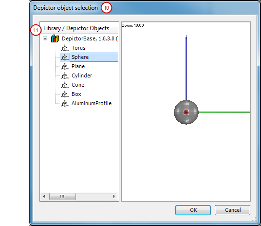
The Depictor object selection dialog opens for selecting a Depictor reference (10):
All Depictor objects that were inserted in the POU pool directly or as a library appear on the left (11). Clicking an object entry opens a preview of the project on the right. The preview works in the same way as for the other 3D views in the CODESYS Depictor Editor (or the CODESYS Depictor Viewer). Click OK to reference the selected object.
Note the following option: You can "publish" individual poses in the POU pool from the properties editor of an object. When you reference such an object from the pool in an element, the published poses appear below the element in the tree and can still be adapted individually. For example, this allows the later addition and customization of more grippers of a defined base articulated arm robot in all areas of use.
Auto-Reload(5): Available only if the geometry source is type File Ref.. Time interval for reloading the referenced file (in milliseconds)
Translation / Rotation / Scale (6): You can define additional static X/Y/Z-transformations for the element. To do this, specify the numeric value in the text fields:
Translation:TX, TY, TZ
Rotation: RX, RY, RZ
Scale: SX, SY, SZ
Interface variables (7): For operation, see the help page for the CODESYS Depictor Viewer: "View 'Properties'".
Appearance tab (1):
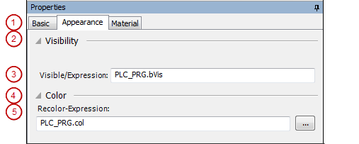
Visibility (2): Visible/Expression (3): The element is visible when the specified Boolean variable or Expression of the application or of the Depictor object is TRUE.
Color (4): Recolor expression (5): The element is recolored entirely with the color specified here. Neither textures are used, nor known colors from referenced CODESYS Depictor objects. To specify the color, you can provide an application variable of type STRING (example: Application.PLC_PRG.strCol) or the exact color value (example: 16#FFFF8040). To open the default dialog for color selection, click the button after the input field. Note: Recoloring does not affect elements below published poses.
Material tab (1):
This tab is available only for elements that are not inserted as Depictor references.
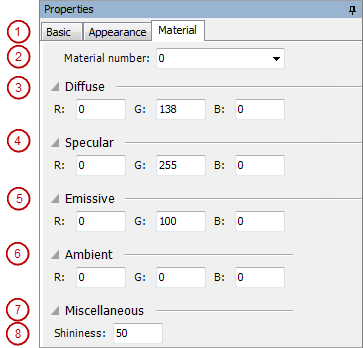
Material number (2): Designates a material in the model
The following material properties can be modified here:
Diffuse
Specular
Emissive
Ambient
Shininess
Depictor Objects in CODESYS Application Composer
In CODESYS Application Composer, you can link declared modules to Depictor objects. This allows for displaying the module tree as a 3D model.
Interface view of a Depictor object in the POU pool
You can create an interface for Depictor objects that are located in the POU pool of the project. When you open this kind of object in the CODESYS Depictor Editor, another Interface view is available, by default hidden as a tab on the left edge of the editor. It contains the Depictor declaration editor.
Declare input variables for the Depictor object, as is usual for function blocks in CODESYS. Every variable declared in the interface is available within the Depictor object, for example to be linked to transformations of poses. When you reference the Depictor object in an element in the tree (Depictor Ref.), the variables are listed in the Interface variables section of the properties editor. You can populate them there with values or expressions for the use case.
Tip
Populating the interface variables is possible in both the CODESYS Depictor Viewer and the CODESYS Depictor Editor.
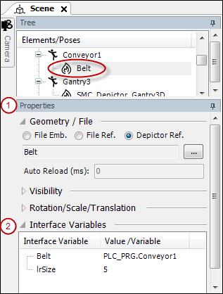
A Depictor object named "Belt" is created in the POU pool of the project and the interface is defined as follows:
VAR_INPUT
        Belt: Conveyor;
        lrSize: LREAL;
END_VAR
When referencing the "Belt" object in a Depictor element, you can populate the variables with values or application variables in the properties editor (1) in the section Interface variables (2):
Camera View
The  Camera view has two sections: Camera Positions and Camera Properties:
Section 'Camera Positions'
The camera positions that are used in the 3D view of a CODESYS Depictor object are saved listed according to the object. A position can be applied from the 3D view into the dialog, as well as from the dialog into the view. Using implicit variables, you can access the camera positions in the IEC code.
A camera position is defined by:
Index: Integer numbering starting at
0Eye: Vector coordinates for the camera position
Target: Camera target
Up: Viewing angle of the camera
The context menu of a selected camera position contains the following commands, in addition to the standard commands (delete, cut, paste, and copy).
 Move Cam Position Up: Moves the position in the table one unit up
 Move Cam Position Down: Moves the position in the table one unit down
- Get camera position: If the 3D view allows straight interactions, then the camera position detected in the 3D view is listed in the camera positions in the Camera view.
- Set camera position: If the 3D view allows straight interactions, the position selected in the list of camera positions is set in the 3D view. The 3D view adapts accordingly.
Access to camera positions from the IEC code:
If version 1.0.1.0 or higher of the library DepictorBase is linked in your project, then every CODESYS Depictor object automatically generates a GVL <name of Depictor object> with the Camera variable.
The Camera variable contains the subcomponents Position of type DepictorBase.DepictorCameraPosition and xUsePosition of type BOOL. Depending on the individual configuration of the Depictor object, Camera may also contain an array pCameraPositions of type ARRAY ... OF DepictorBase.DepictorCameraPosition. This array describes defined camera positions of the object. The number of camera positions in the array is defined by the variable uiNumberOfCameraPosition of type UINT.
Using these implicit variables, you can control the camera with the IEC code. When creating the code, use the function "List Components" for getting access to the subcomponents of <Depictor object>.Camera. The positional information from the IEC code are use only if you set xUsePosition to TRUE, Then direct interaction is no longer possible in the 3D view. The is indicated by a red frame around the view.
The library receives both the InterpolateCameraPosition function block and the DepictorCameraPosition structure for defining a camera position,. This block is used for interpolating to a new DepictorCameraPosition within the defined time. This allows animated camera motion as soon as a new position is set.
Section 'Scene Background'
Background color | Color for the background of the scene; can be set in the default list box of colors |
Activate Skydome with following Texture |
|
Import Texture | Opens the default dialog for selecting a file for the texture. Possible file types: |
Clear Texture | The specified texture file is removed from the settings. |

Section Camera Properties
Use camera automatic |
|
Close level | If an object is closer than this layer, then it is not displayed anymore. |
Far layer | If an object is farther than this layer, then it is not displayed anymore. |
Field of view (FOV) | Field of view: Opening angle of the camera. |
Lighting View
In the lighting view, you can configure multiple light sources for lighting a scene in the 3D view. Each light source is shown as a node in the table with its properties below it.
For this, also see below: Example of the 3D view, bird's eye view, and lighting configuration.
Use automatic lighting | Six light sources are placed automatically on the X/Y/Z-axes around the 3D objects so that the scene is lighted optimally according to the used materials. |
Light / Property | Value |
|---|---|
Light type | Type of light source
|
Position | X/Y/Z-values of the light source in the coordinate system (for example, |
Diffuse Color | Color of the diffuse light in the lighting; Example: |
Specular Color | Color of the mirrored light in the lighting (for example, |
Ambient Color | Color of the ambient light in the lighting (for example, |
Radius | Maximum diffusion radius of the light |
Constant Attenuation | Value for the constant fading of the light in the path of the light radius |
Linear Attenuation | Value for the linear fading of the light in the path of the light radius |
Quadratic Attenuation | Value for the quadratic fading of the light in the path of the light radius |
Direction | Direction of the light for light sources of types Directional and Spot |
Falloff | Light falloff in the path from the inner to outer cone for the light source type "Spot" |
Inner Cone | Radius of the inner light cone for the light source type "Spot" |
Outer Cone | Radius of the outer light cone for the light source type "Spot" |
The context menu of a  light source node contains the following commands, in addition to the standard commands (delete, cut, paste, and copy).
 Set light to camera position/direction: The position and direction of the light source contain the same values as the camera.
 Show light radius in bird view: The radius configured for the light source is shown in color as a raised circle in the bird’s eye view.
Bird's eye View
The  Bird's eye view provides an overview of the current scene in the 3D view. The camera is shown as a gray cylindrical object and the light sources as yellow conical objects.
For this, also see below: Example of the 3D view, bird's eye view, and lighting configuration.
As in the 3D view, you can move the mouse to change the viewing angles of the entire scene. However, the camera position always remains on the Z-axis of the scene. Zooming only changes the distance from the camera to the center.
When you select the Show the light radius in the bird's eye view option in the Lighting view for a light source, the lighted area is displayed as a yellow circle.
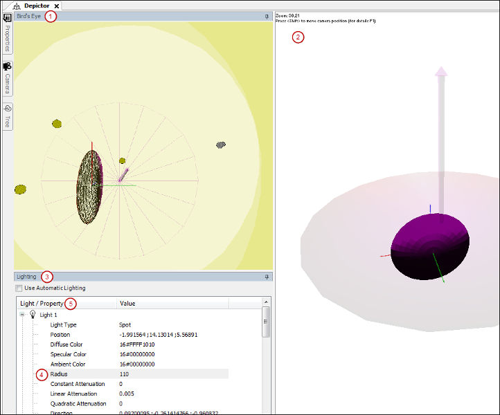
Example of the 3D view, bird's eye view, and lighting configuration
See the example in the following image for a pose in the bird's eye view (1) and in the 3D view (2). By configuring the lighting view (3), the scene also gets three light sources (5) that can be seen as yellow objects in the bird's eye view. The radii (4) of the light sources are displayed as yellow overlapping circles around the object in the bird’s eye view. The camera is shown as a gray conical object in the bird’s eye view. The shadowed circular area with the arrow axis in the 3D view is also in the bird's eye view, and the object is also drawn as a frame model. This helps to detect the current viewing direction of the camera on the object in both views.