Creating a Device Project with CODESYS Control Win V3 x64 in Structured Text and Ladder Diagram
In this chapter, you will create a small CODESYS 4 project. You will start with a blank screen and at the end you have a working program that you can watch live. You will learn how to create a workspace with a device project and afterwards know where these are located in the new environment.
The project describes a fan control unit. When the temperature exceeds a maximum value, a fan is switched on and the temperature falls. When the temperature falls below a minimum value, the fan switches off and the temperature rises. The temperature is simulated by the program.
Steps in this tutorial
Create a workspace with a device project
Program code in Ladder Diagram (LD) and Structured Text (ST)
. Included programsFB_FanControl(LD): Control unit which switches the fan on above 30 °C and switches off below 25 °CPLC_PRG(ST): Simulates the temperature using a timer and calls the control unit
Create the application
Download the application to the controller CODESYS Control Win V3 x64
Observe the application in online mode
Requirements
CODESYS 4 is installed on your computer. The setup already includes the "Ladder" extension.
For more information, see the following: Installation as a Desktop Application for Windows
The SoftPLC CODESYS Control Win V3 x64 is installed and running.
Starting CODESYS 4
In the file explorer, open the installation directory of CODESYS 4.
Run the
CODESYS-4.exeprogram.The programming interface will open.
Create Workspace
Note
In this tutorial, all files belonging to the project will be created in D:\TemperatureControl\ as an example. You can choose any location.
Select the Menu → Create Workspace command or click the
 button in the workspace navigator.
In the Select a Path for the Workspace File dialog, specify the following:
Workspace name:
TemperatureControlPath: Click the
 button.
For Entry point, choose the "D" drive.
Use the New Folder command to add the
TemperatureControlfolder, then select it, and click the Select Folder button.
Click OK.
The workspace will be created and opened. The Add Project to Workspace dialog will open.
Create Device Project
In the Add Project to Workspace dialog, select the Create Device Project command.
Note
If the Add Project to Workspace dialog is not open, then select the Menu → Create Device Project command.
In the Create a new Device Project dialog, specify the following:
Path:
D:/TemperatureControl/Project name:
FanControlAs an option, you can add more information.
Click Create.
In the Add PLC dialog, select the CODESYS Control Win V3 x64 controller.
Click OK.
In the Add program dialog, select Structured Text (ST) as the implementation language. Click Create.
The wizard will close and the workspace navigator will display the
FanControl.fbsdevproject with theDevicesandApplicationitems. ThePLC_PRG.prg.stprogram will be created belowApplication.
Resolving libraries
For temperature simulation, we need a timer which is included in the Standard library. A new device project references the Standard library by default. The libraries will be automatically resolved one time while the project is being created. For this project, we do not need to resolve the libraries again because we are not including any other libraries.
However, we will explicitly resolve the libraries again in order to observe the notification output.
In the navigator, right-click
Libraries.jsonand select the Resolve All Libraries command.In the lower area, open the LIBRARY RESOLUTION view to check the notifications.
Creating the fan control unit
Right-click the
Applicationitem and select the Add Item → Function Block command.Choose the name
FB_FanControland select Ladder Diagram (LD) as the implementation language.Click Create.
In the declaration part of the function block, declare the interface:
FUNCTION_BLOCK FB_FanControl
VAR_INPUT
    // current temperature
    temperature : LREAL;
    // switch ON  at/above this value
    onLevel : LREAL;
    // switch OFF at/below this value
    offLevel : LREAL;
END_VAR
VAR_OUTPUT
    // indicates whether the fan should be turned on
    fanOn : BOOL;
END_VAR
Create a network named
Fan Controlas shown in the following figure.Tip
If you are not familiar with the LD editor, then read chapter Programming in the Ladder Diagram first.
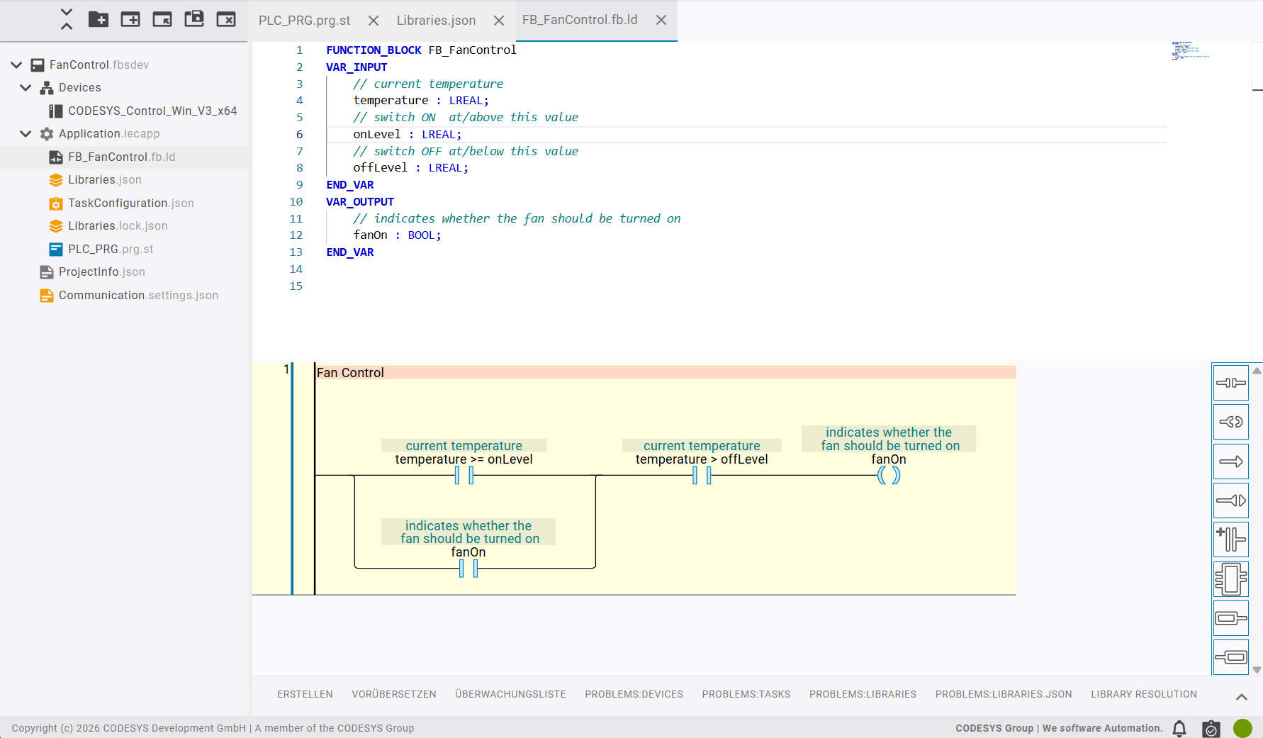
The network corresponds to the following expression:
fanOn := (temperature >= onLevel OR fanOn) AND (temperature > offLevel);
. Components of the network:A comparison contact with the condition
temperature >= onLevelParallel to that and below, a self-holding contact
fanOnIn series with this, a comparison contact with the condition
temperature > offLevelA coil
fanOn
The network works in such a way that the fan will switch on at a temperature greater than
onLevel(30 °C). Via the self-holding contactfanOn, the fan will remain switched on until the temperature drops belowoffLevel(25 °C).
In
PLC_PRG.prg.st, the simulation of the temperature over time will be implemented, as well as the passing of the current value to the control unit.Tip
The autocomplete feature will help you as you type. For example, if you type
tick : TON, a list of suggestions will be offered. When you click the arrow on the right of a suggestion, help text will be displayed which describes the timer.In the implementation, if you type
fanControl(, the autocomplete feature will show its parameters and the descriptions which you specified in the function block. In this way, you always know which value belongs where.Open
PLC_PRGand specify the following program:PROGRAM PLC_PRG VAR // 500 ms heartbeat tick : Standard.TON; // two-point fan controller (LD) fanControl : FB_FanControl; // simulated temperature [°C] temperature : LREAL := 22.0; // fan command fanOn : BOOL; END_VAR // implementation here... // 1) Heartbeat: TRUE for one cycle every 500 ms tick(IN := NOT tick.Q, PT := T#500MS); // 2) On each tick the temperature drifts: the fan cools, otherwise it heats up IF tick.Q THEN if fanOn THEN temperature := temperature - 1.0; ELSE temperature := temperature + 1.0; END_IF END_IF // 3) The controller decides whether the fan runs (ON at 30 °C, OFF at 25 °C) fanControl(temperature:= temperature, onLevel:= 30.0, offLevel:= 25.0, fanOn=> fanOn); END_PROGRAM
The clock
tickgenerates a pulse every500 ms. With each pulse, the temperature changes by one step. When the fan is running, it will drop. Otherwise, it will rise.Right-click the
Application.iecappitem and select the Build Application command.CODESYS 4 compiles the project.
In the BUILD output, check that the project has been compiled successfully.
Downloading a program to the controller
Double-click the
Communication.settings.jsonitem.The Communication Settings will open in the editor.
Click the Configure Device button.
The Device Browser dialog will open, displaying the available controllers.
Tip
If you do not see a device in the list, then the SoftPLC is most likely not running. Check the tray icon of CODESYS Control Win V3 x64 and start the controller if necessary.
Click the Refresh icon next to the search bar in order to scan the network again. The Connect Device command tests the connection to the selected controller and reports whether it can be reached. Your controller should now be listed.
Select your controller and click the Connect Device button.
Because a user management has not been set up on your device yet, the Create Initial User for Device dialog will open.
In the Log In to Device dialog, provide your credentials and click Log In.
The notification Connection successful will be displayed.
In the Device Browser dialog, click Select.
Right-click Application.iecapp and select the Download Application command.
Right-click Application.iecapp and select the
Log Incommand.Enter your credentials if necessary.
In the Confirm Download dialog, click Download.
A notification Login successful will be displayed. The display in the upper right corner changes as follows:

Open the PLC_PRG program in the editor.
The inline monitoring in the editor will display the current values directly after the variable.
Watch the values in the WATCHLIST: in the lower view, switch to the WATCHLIST tab. The WATCHLIST is still empty.
Add 2 expressions and select each of the Application entries in the Application column:
PLC_PRG.temperaturePLC_PRG.fanOn
In the top-right corner in the window, click the
 button to start the active application.
The values of monitored variables will be displayed.
What you have achieved in this tutorial
You have created a workspace with a device project.
You have programmed an ST program and included a function block from a standard library.
You have programmed an LD function block.
You have compiled the application without errors and downloaded it to the controller.
You have observed the variables in the WATCHLIST.
Continue with the Outsourcing Function Blocks to a Library tutorial.