Creating an Alarm Class
Basic settings such as the priority, the acknowledgement method, the notification actions, and the display options are configured in an Alarm Class object.
The following predefined alarm classes are available:
Alarm class: Error
Alarm class: Info
Alarm class: Warning
Priority
Prioritization is intended to make sure that all alarms are structured according to their importance and urgency.
Acknowledgement method
The acknowledgement method defines the expected alarm handling for the visualization user. The states and state transitions which an alarm of this class can have are defined by selecting the acknowledgement method.
The initial situation is that an alarm has been triggered and is now active. Then the following acknowledgement methods are possible:
Acknowledgement method: ACK
The visualization user acknowledges the alarm either with either "
ACK" or "confirm". Then the alarm returns to its normal state. This is the method for events. ("Events")The following state transition chart shows the acknowledgement with "
confirm".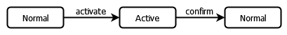
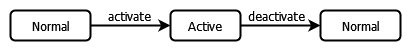
Acknowledgement method: REP
After the visualization user has resolved (repair) the cause of the alarm, the alarm automatically returns to the normal state.
Acknowledgement method: REP_ACK
After the visualization user has resolved (repair) the cause of the alarm, the system waits until the visualization user acknowledges this with "
confirm". Then the alarm returns to its normal state.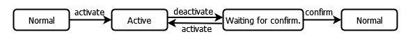
Acknowledgement method: ACK_REP
Situation 1: After the cause of the alarm has been resolved (and the alarm has been deactivated), the system waits for the visualization user to confirm with "
confirm". If the alarm is triggered again during this time, then the alarm becomes active again and the visualization user must deactivate the alarm. Then the alarm returns to its normal state.Situation 2: The visualization user acknowledges the alarm with "
ACK". The alarm goes into the "Active, Acknowledged" state until the cause of the alarm is resolved and the alarm is deactivated. In the meantime, the alarm can be triggered again. The visualization user must confirm this if it happens. Then the cause of the alarm can be resolved and the alarm can return to its normal state.The following state transition chart shows the flows for the two situations.
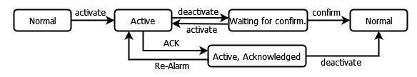
Acknowledgement method: ACK_REP_ACK
Situation 1: After the cause of the alarm has been resolved (and the alarm has been deactivated), the system waits for the visualization user to confirm with "
confirm". If the alarm is triggered again during this time, then the alarm becomes active again and the visualization user must search again for the cause of the alarm and resolve it. When the visualization user confirms the resolution with "confirm", the alarm returns to its normal state.Situation 2: The visualization user acknowledges the alarm with "
ACK". The alarm goes into the"Active, Acknowledged" state until the cause of the alarm is resolved and the alarm is deactivated. In the meantime, the alarm can be triggered again ("Re-Alarm"). The visualization user must confirm this if it happens. Then the visualization user must resolve the cause of the alarm. However, the alarm does not return to the normal state, but waits for acknowledgement. The alarm returns to its normal state only after the visualization user has confirmed with "confirm".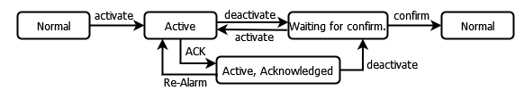
Tip
When you move the mouse pointer over the possible acknowledgment methods in the expanded list box in the editor, the respective state transition chart is displayed on the right side.
Change of acknowledgement method via online change
Note
This is possible only if supported by your device.
Changes made via online change may modify the acknowledgement method for active alarms. This can cause alarms to be triggered in unexpected states. In this case, the operation will continue based on the new acknowledgement method.
An example of this is the change in the acknowledgement method from ACK_REP_ACK to REP. An active alarm in the "Waiting for Confirmation"" state then immediately switches to the "Normal"" state because the new method does not require acknowledgement.
Notification Actions
You use the notification actions to define which actions (also multiple) should be executed for the respective state transitions.
Configuring an alarm visualization
In the Display Options for Alarm Table/Alarm Banner group, you can configure the display settings for the alarm class. The display which is visualized with the alarm elements is configured in the table depending on the possible alarm states. The configured layout should correspond to the respective alarm state in terms of font, font color, and background.
Step-by-step configuration of a new alarm class
In the section below, you configure an example AC_PartsShortage alarm class in which all of its derived alarms inherit its properties. Triggered alarms of this class set the bPartsShortage variable to TRUE. When the Alarm Table visualization element is programmed, in the event of an alarm the triggered alarms are highlighted in red and the unconfirmed alarms are highlighted in yellow.
AC_Partshortage alarm classIn the device tree, select the
Alarm Configurationobject.Click the command. Specify the name
AC_PartsShortage.After it is added, the new
AC_PartsShortagealarm class is displayed in the device tree. The object opens in the editor.Configure the alarm class as follows:
Priority: 10
 Archiving
The triggered alarms are archived at runtime.
Note: When you define alarms with this kind of alarm class in an alarm group, you also need to assign an object for alarm storage to this alarm group. Otherwise archiving will not work.
At runtime, all state transitions of alarms of the alarms are permanently stored in an SQLite database. At the same time, the contents of the database can be displayed as an alarm table. For this, the
Historycontrol variable of the alarm table must be set toTRUE.Acknowledgement method:
REP_ACK- Acknowledge separately
The visualization user must acknowledge each alarm of this class individually.
Configure a notification action for the state transitions as follows:
In the Notification Actions group, double-click in the Action column.
Select the Variable action and press the Enter key to confirm your selection.
Input fields will be displayed below the list of notification actions in order to configure the new action.
In your IEC program, declare the
bPartsShortagecontrol variable If necessary and enter it in the Variable input field. In the input field on the right, specify the valueTRUE.
The action is inserted. By default, the Deactivate and Confirm state transitions are selected. This means that the variable action is executed for both state transitions and the variable is automatically set for both transitions.
A summary of the configuration is displayed in the Details column:
PLC_PRG.bPartsShortage := TRUE.Leave the option in the Activate column selected, and clear the Deactivate and Confirm state transitions.
The action is only executed with the "
activate" transition.In the Display Options for Alarm Table/Alarm Banner group, configure the alarm display for the visualization as follows:
Configure the display for the Active state:
Double-click the corresponding cell in the Active row and the Background Color column. Select red as the color.
Double-click the corresponding cell in the Waiting for confirmation row and the Background Color column. Select yellow as the color.
The
AC_PartsShortagealarm class is programmed.