Creating the User Interface for Distributed Alarm Management
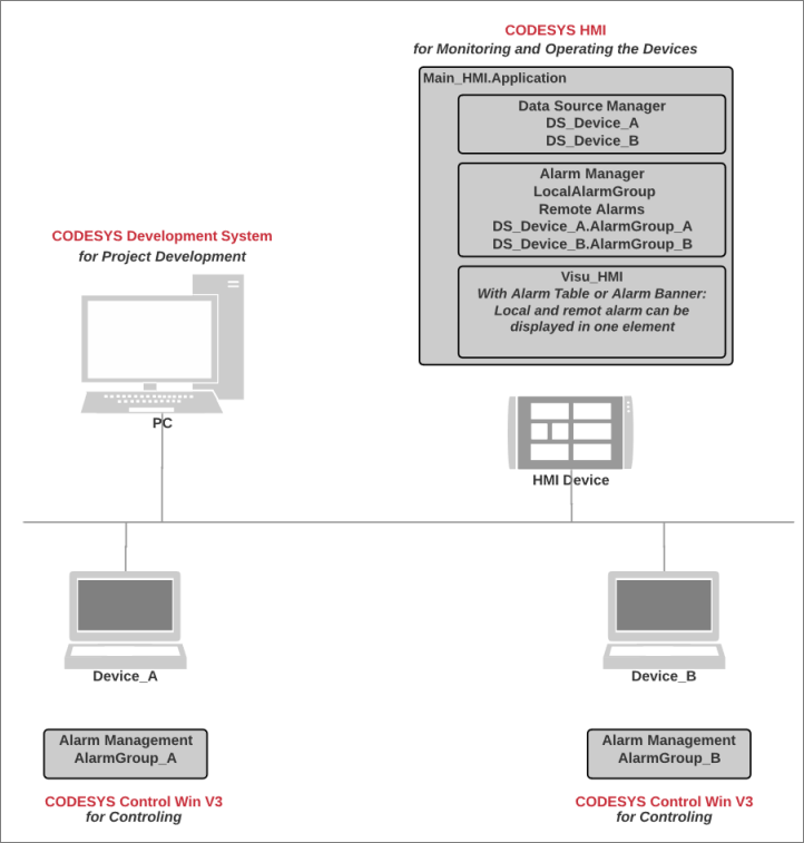
You can create an application with distributed alarm management on an HMI device. Distributed alarm management means that both alarms that occur on the local device and alarms that occur on devices in the network are processed centrally. The alarm information is exchanged via data source connections, each of which is extended by a proxy server. For the alarm information, you can create a visualization which can display all alarms in the network in a single alarm element. This allows the user to monitor all devices in the network from a central location in a clearly organized visualization in one alarm element.
The following sections describe step-by-step how to create an HMI application with alarm visualization for networked PLCs.
Remote applications in the network
Initial situation: In your network, you have multiple PLCs whose applications (in addition to controller programs) each have their own alarm management. In the applications, the alarm conditions are checked and alarms are triggered if applicable. The alarm information is recorded. These remote applications are running (green and marked [run]).
The following image shows an example of such a network.
Tip
If you add alarms in an alarm group on a remote PLC without subsequently updating the HMI application, then incorrect or incomplete displayed alarm information may be transmitted. This also happens when you add alarm classes or alarm groups on a remote PLC below an alarm configuration.
Therefore, we recommend that you update the HMI application after changes are made in a remote alarm configuration.
Creating the HMI application
In the Devices view, select the top node
DistributedAlarmManager.Click .
The dialog opens.
Select CODESYS HMI as the HMI device.
Specify a name (example:
Main_HMI).Click the Add Device button.
The device is created.
In the Devices view, select the application.
Click .
Select the new object and insert a data source below it for each remote PLC. Select a connection (example: CODESYS Symbolic).
The data source connections to the remote PLCs are configured.
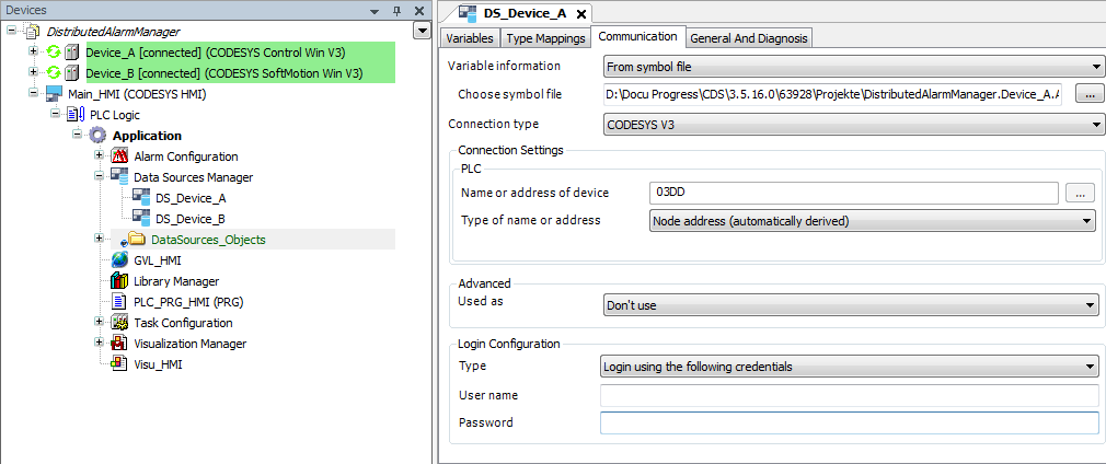
A connection to the remote devices is available via the data sources
DS_Device_AandDS_Device_B. Now the alarm configuration can be extended.Tip
For a description of all options regarding how to set up data source connections, see the chapter "Data Source Manager".
Setting up a local alarm configuration
In the Devices view, select the HMI application.
Click .
Select the new Alarm Configuration object and click .
The Add Remote Alarms dialog opens. The Add all available alarm classes and groups option is selected.
Confirm the settings and click Add.
The Remote Alarm object is inserted below the alarm configuration. The remote alarm managements are displayed in the editor. The information is prepared by the data sources.
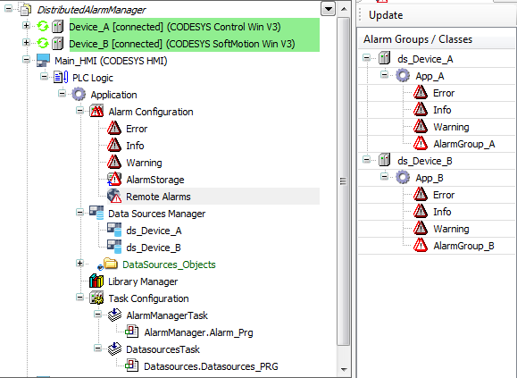
Below the alarm configuration, add a local alarm group
LocalAlarmGroupand define alarms there.Example:
In this example, the alarm variables are declared globally in
GVL_HMI.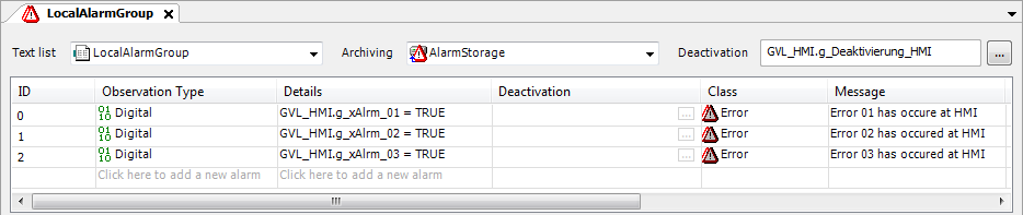
The local alarm configuration of the HMI allows for access to local and remote alarm information. Alarm information is exchanged via proxy servers which are started for each data source. The alarm management is distributed.
Now you can create a visualization with the Alarm Table or Alarm Banner elements.
Visualizing with an alarm table
Add a visualization below the application.
Drag the Alarm Table element to the visualization.
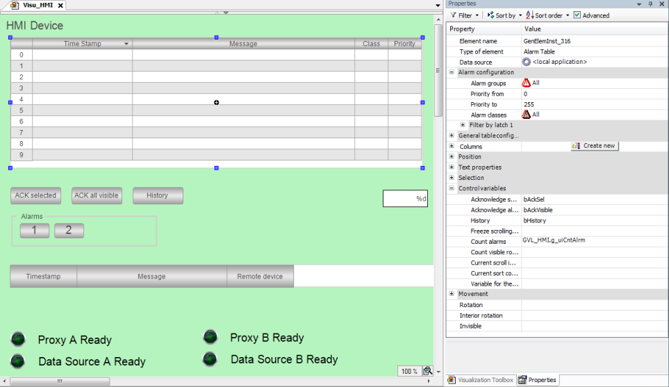
Configure the following properties:
Property: Data source: <local application>
The alarm element is assigned to the local alarm configuration. Because the local alarm configuration has the Remote Alarms object, remote alarm information can also be visualized.
Select the Advanced option in the Properties view.
All visualization properties of the alarm table are visible.
In the interface editor, declare control variables for the visualization.
VAR bAckSel : BOOL; bAckVisible : BOOL; bHistory : BOOL; uiCntAlrm : UINT; END_VAR- . Configure the Control variables property as follows:
Control variables, Acknowledge selected property:
bAckSelControl variables, Acknowledge all visible property:
bAckVisibleControl variables, History property:
bHistoryControl variables, Count alarms property:
uiCntAlrm : UINT;
The Acknowledge selected control variable is responsible for the acknowledgment of alarms that are selected in the table.
The Acknowledge all visible control variable is responsible for the acknowledgment of visible alarms.
The History control variable activates the display of variables in historical order.
Drag the Button element to the visualization three times.
Configure the buttons.
. First button:Texts, Text property:
Acknowledge SelectedInput configuration, Toggle property:
bAckSel
. Second button:Texts, Text property:
Acknowledge All VisibleInput configuration, Toggle property:
bAckVisible
. Third button:Texts, Text property:
historical DisplayInput configuration, Toggle property:
bHistory
The alarm table is configured. The user can use the buttons to acknowledge the alarms.
Visualizing with alarm banners
Open the visualization.
Drag the Alarm Banner element to the visualization.
Configure the element with the following settings:
Property: Data source: <local application>
The following settings are set automatically:
Alarm configuration,Alarm groups property: All (default)
Alarm configuration,Alarm class property: All (default)
Running the HMI application
Requirement: The applications have been downloaded to the remote PLCs and are running.
Click the
 symbol.
The HMI application is compiled.
Click the
 symbol.
The application is downloaded to HMI device. The data source connections to the remote devices are established. The proxy servers of the data sources start.
Click the start
 symbol.
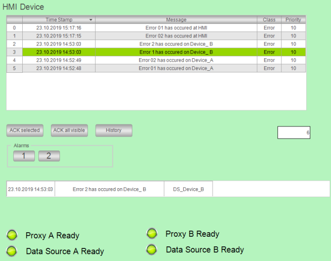
The HMI application is executed. The visualization starts. As soon as all proxy servers are active, all alarms distributed in the network are displayed centrally in the alarm element. The user can acknowledge the alarms centrally.
Example:
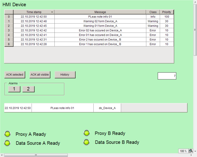
A visualization is running on the HMI device and has distributed alarm management (set up in the local alarm configuration) which exchanges information with remote alarm managements via data source connections. All alarms of a network are displayed together in an alarm table. The alarm element displays all alarms as you have configured in the local alarm configuration in the "Remote Alarms" object. This results in a uniform display of the alarms. You can also have the remote display options transferred and accepted.