Using HMI to Centrally Visualize Remote Alarms
If multiple devices are connected over a network (via data source connections) and an HMI device is connected in the network, then an alarm management for distributed alarms is possible in the HMI application.
The HMI device has a connection via the data source management to the devices in the network, each of which manages its own alarm. In order for the transmission of the remote alarms to the local HMI alarm management to be possible, you add a Remote Alarms object to the local alarm management. This object mirrors the remote alarms (active and recorded) into the HMI at runtime.
On this basis, you can display the local alarms and the alarms of the remote devices centrally in a single alarm visualization (alarm table / alarm banner) on the HMI device.
The alarm recordings are stored directly on the controller where the application is also running.

Configuring remote alarms
You can configure an application with alarm management for remote alarms for an HMI device.
The local alarm configuration of the HMI is extended by the Remote Alarms object. Then the alarm system can process not only local alarms but also remote alarms and display their alarm information. Meanwhile, the remote alarms are connected to the HMI device via the data source management. The visualization of the HMI application can centrally display the alarms in the network. The user can acknowledge and react to these at a central location.
In the following instructions, the Remote Alarms object is configured as an example.
Initial situation: Applications are running on remote PLCs in the network. Each of these applications has a configured alarm management and the Alarm Configuration object is available in the Devices view below the application.
On you local system, start an HMI runtime.
Open CODESYS and click the File → New Project command.
Select the HMI Project template and specify a name
Central_HMIfor the new projectSpecify the communication settings of the HMI runtime.
In the Create HMI Project – Add Objects dialog, select the Alarm configuration and Program objects.
For the perspective, select the CODESYS Perspective.
The project
Central_HMIhas been created.Select the data source manager and insert a data source there for each remote PLC. For the connection, select CODESYS Symbolic.
Important
Remember that the applications of the remote PLCs must be active. Therefore, download and start the remote applications in time and check their state.
Connections to the remote devices are available via the data sources
ds_Device_Aandds_Device_B. Now the alarm configuration can be extended.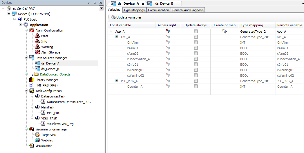
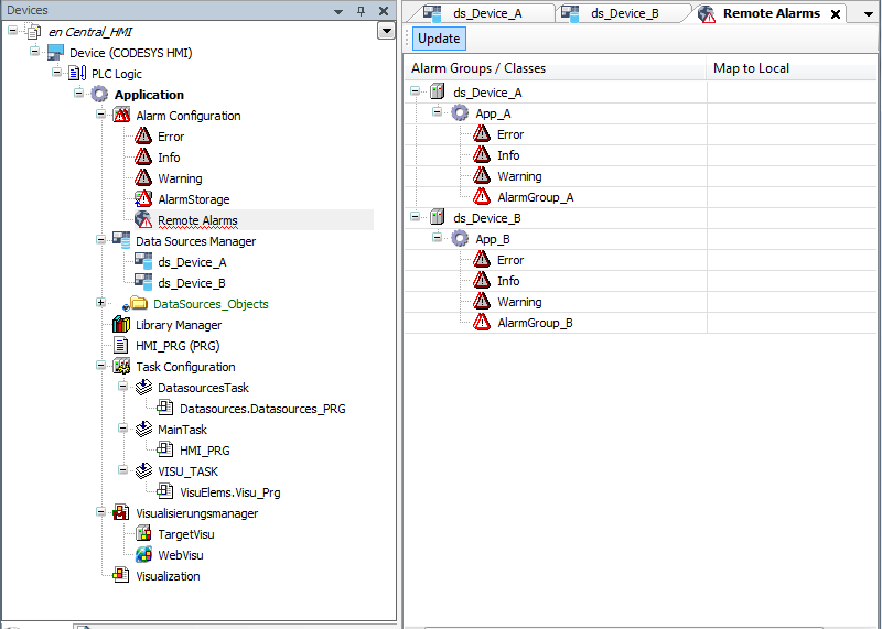
Select the alarm configuration and click the Add Object → Remote Alarms command.
Click Add to confirm the dialog.
The local alarm configuration has been extended with the information from the alarm configurations of the applications
App_AandApp_B. The alarm management is distributed and communicates via the data source connections. Now the local HMI application can be downloaded to the CODESYS HMI runtime.In addition, you can create a visualization with the Alarm Table or Alarm Banner elements.
Connecting to the alarm management of a remote PLC
With an HMI project, you can display the alarms of a remote PLC in the "alarm table" visualization element. Requirement: Alarm management is defined in the remote PLC.
Connecting an HMI application to a controller
Open the initially created HMI project.
Select the Data Sources Manager object.
Click the Add Object → Data Source command.
The Add Data Source dialog opens and helps you to configure the data source. The CODESYS Symbolic data source type is set by default. You use this type if your control application has a symbol configuration.
Specify a name for the data source. Example:
Data_Source_Alarmand click Add.The Initialize Data Source Wizard – Provider settings dialog opens.
The
CODESYS V3connection type is set by default.In Name or address of device, specify the network name of the active controller whose data you want to visualize. Example:
Device_AThe connection from the development system to the controller is established and the available variables are read. The Initialize Data Source Wizard – Browse data items dialog opens. The variables of the
Device_Acontroller that can be accessed are listed in a table.For the visualization of data from a remote alarm manager, you need to activate non-explicit variables. The required data is exchanged between the HMI and the remote device via internal communications services.
Click Finish.
The data source is created initially and inserted below the data source manager.
Creating a visualization of an alarm table
Now create your visualization as usual. Open the editor for the visualization and add the Alarm Table element.
Select the element.
Configure the following settings in the Properties view:
:
Data_Source_Alarm:
ApplicationSelect the alarm table and click the Visualization → Add Elements to Alarm Acknowledgement command.
The Alarm Table Wizard dialog opens.
Activate all actions and close the dialog.
Additional buttons are added to the alarm table.
Running the HMI application
Click the
 symbol.
The application is compiled.
Click the
 symbol.
The application is downloaded to HMI device.
Click the start
 symbol.
The HMI application is executed. The visualization starts.
The Alarm Table element shows the active alarms of the remote PLC. You can acknowledge the alarms and also switch to the "History" view.