Configuring Movement and Rotation
You can animate a visualization element so that is moves or rotates at runtime. To do this, you assign variables in its property and program the animation in the application code.

Configuring a movement
You can configure the movement of an element by programming the variable in Absolute movement → Movement.
Requirement: A project with a visualization is open.
Open the visualization editor and add a Rectangle element.
The Properties view shows the configuration of the element.
In the application, declare type-compliant variables in the
PLC_PRGPOU.Declaration in ST
PROGRAM PLC_PRG
VAR
    diOffsetX : DINT;
    diOffsetY : DINT;
END_VAR
Configure the Absolute movement → Movement property.
X with
PLC_PRG.diOffsetXY with
PLC_PRG.diOffsetYImplement a movement of the element, for example by a modulo division of the value:
Implementation
PROGRAM PLC_PRG
VAR
    diOffsetX : DINT;
    diOffsetY : DINT;
END_VAR
diOffsetX := diOffsetX MOD 100; diOffsetY := diOffsetY MOD 100;
Compile, download, and start the application.
The application runs. The visualization opens. The rectangle moves.
Rotation around a fixed point
An element can be rotated around a fixed point. Under the Center property, define the fixed point with X/Y coordinates. The midpoint of the element is calculated internally. The alignment of the element is does not change with respect to the coordinate system.
When the visualization is run, the element is moved so that its midpoint draws a circular path around the fixed point (center).
Tip
Note that no movement occurs in a configuration where the midpoint and center coincide.
Requirement: A project with a visualization is open.
Open the visualization and add a Rectangle element.
The Properties view shows the configuration of the element.
In the application, declare a type-compliant variable in the
PLC_PRGPOU.Declaration in ST
PROGRAM PLC_PRG
VAR
    rValue : REAL;
END_VAR
You can configure a right rotation of the element by setting the Absolute movement → Rotation property with a variable whose value is increased programmatically.
Configure the Absolute movement → Rotation property.
Rotation with
PLC_PRG.rValueImplement the clockwise rotation of the element by increasing the value of the variable in your IEC code.
Implementation
PROGRAM PLC_PRG
VAR
    rValue : REAL;
END_VAR
rValue := rValue + 0.1;
Compile, download, and start the application.
The application runs. The visualization opens. The rectangle rotates about the center. The alignment of the element is fixed according to the coordinate system.

Rotating element
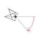
Interior rotation
An element can also perform a self-rotation. To do this, configure the Interior rotation property. Under the Center property, define the fixed point with X/Y coordinates. The midpoint of the element is calculated internally. In addition, the position changes of the element must be programmed.
When executed, the element rotates around this fixed point. Then the alignment of the element rotates with respect to the coordinate system.
Tip
Note that the element rotates at the position when the midpoint and center coincide.
Requirement: A project with a visualization is open.
Open the visualization and add a Polygon element that you shape into a pointer.
The Properties view shows the configuration of the element.
In the Position → Angle property, specify a static angle of rotation.
The angle of rotation has an initial value.
Drag the center point of the element to the base of the pointer.
In the application, declare a type-compliant variable in the
PLC_PRGPOU.Declaration in ST
PROGRAM PLC_PRG
VAR
    rValue : REAL;
END_VAR
You can configure a right rotation of the element by setting the Absolute movement → Rotation property with a variable whose value is increased programmatically.
Configure the Absolute movement → Interior rotation property.
Interior rotation with
PLC_PRG.rValueImplement the clockwise rotation of the element by increasing the value of the variable in your IEC code.
Implementation
PROGRAM PLC_PRG
VAR
    rValue : REAL;
END_VAR
rValue := rValue + 0.1;
Compile, download, and start the application.
The application runs. The visualization opens. The pointer rotates about its base. The angle of rotation increases continuously starting at the position that determines the static angle of rotation, because the static angle of rotation is added to the angle of rotation. The static angle of rotation acts as an offset.