Element: State
A state is the main element of a statechart. A state machine (or statechart) runs through various states during its runtime and executes their actions. A state can have ENTRY, DO, and EXIT actions which are executed at specified times during the runtime of the state.
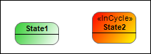
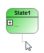
A state is represented as a green box with rounded corners. An in-cycle state is displayed in red. You set an in-cycle state in the In-cycle property.
An ordinary state is clocked according to the task in which it is called. The transition to the next state is only switched with the next task cycle.
An in-cycle state switches independently of the task cycle. When the actions of an internal state have been completed, the switch is made to the transition immediately. The condition of the transition is checked and its transition action is executed, and then immediately switched to the end state.
Properties
Property | Description |
|---|---|
Identifier | Name for the element. You can also change the name in the statechart. |
Color | Color of the element. You can change the color using a color selection dialog. Default: green |
Implicit start state |
|
In-cycle |
|
Max DO cycle calls | Maximum number of calls of the DO action. Number between 1 and 32767. When this value is exceeded, the current state switches to the next state. |
ENTRY action | Name of the corresponding action |
DO action | |
EXIT action |


User input
When you select the element, transition icons are visible above the element. You can use these to link states.
Action | Description |
|---|---|
| The name of the element can also be changed in the properties. |
| Note: If you do not click an existing element, but in a blank area, then a new state is created. |
| The action object can be an action or a method. If the action is a method, then you also have to define the return type and the access type in the New Action Object dialog. The assignment to the action object can be changed in the properties of the element. A state can have an ENTRY action, a DO action, and an EXIT action:
TipYou can also add or change the actions or methods in the properties of the element. |
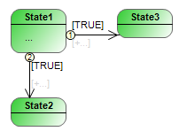
| If a state has more than one outgoing/incoming transition, then its priorities define the order of execution. The priorities are displayed in a small circle. You can change the priority in the properties of the transition. |