Working in the Class Diagram Editor
The class diagram editor provides elements which map the object orientation of the project. Because the editor is embedded in the CODESYS Development System, you can generate code from it automatically. This provides you with extensive integrated features and tools, such as for error detection.
CODESYS automatically keeps the name and properties of objects in the class diagram and in the project the same. Therefore, user input affects both views. A class diagram does not have to represent all objects that are in the device tree. You can remove elements from the class diagram and leave the object in the device tree.
Tip
To get a filtered view of the project, you can intentionally drag only a selection of existing objects from the POUs view or Devices view or Devices view into the class diagram.
Adding new elements to the class diagram
Drag a Class (POU) element from the toolbox of the class diagram to the class diagram editor.
The Add POU dialog opens.
Select the Function block type and specify a name for the new POU (example:
POU_1. Click Add.The element is inserted into the editor as a new box element.
The
POU_1object is added to the Devices view.Drag another Class (POU) element to the class diagram editor. Select the Function block type and specify a name for the new POU (example:
POU_2.The element is inserted into the editor as a new box element.
The
POU_2object is added to the Devices view.Select the
POU_2element.The possible commands are displayed as icons.
Click Generalization (EXTENDS) and drag to the
POU_1element.A connecting line is drawn from
POU_2toPOU_1.The IEC code of
POU_2is adapted accordingly toFUNCTION_BLOCK POU_2 EXTENDS POU_1. ThePOU_2function block extends thePOU_1function block.Double-click the
POU_2element.The object opens in the editor.
Tip
You can drag objects that already exist in the Devices view or POUs view to the class diagram editor. All existing dependencies to other objects are displayed.
Tip
When you add an object, the and commands are no longer available.
Inserting relationships between elements
 : Composition (
VAR) : Association (
POINTER TO)- : Association (
REFERENCE TO)  : Realization (
IMPLEMENTS)- : Generalization (
EXTENDS)
Select the element that you want to link to another element.
Drag the desired element from the ToolBox view to the other element, or click the icon above the element.
A connecting line is displayed.
Note
Right-click to cancel the link.
Click another element or a blank space in the editor.
A dialog opens to add an object or a declaration, depending on the type of link and the "target element".
Removing elements from the class diagram
 : The element is removed from the class diagram only.
 : The element is removed from the class diagram and the project
Tip
If you have removed selected elements from the class diagram and the project, then you cannot reverse this action with the Undo command.
When the elements are removed from the class diagram only, they can be inserted back into the diagram at any time.
Select the element to be deleted.
Press the Del key or click the
icon.A dialog prompt opens with the option to remove the selected elements only from the diagram or from both the diagram and the project.
Select the Delete from diagram option and click OK to exit the dialog prompt.
The class diagram no longer contains the previously selected elements. The respective objects are available both in the device tree and in the POU view.
Select the element to be deleted.
Press the Del key or click the
icon.When you press the Del key, a dialog prompt opens with the option to remove the selected elements only from the diagram or from both the diagram and the project. When you click
, the element is deleted immediately.Select the Delete from project and diagram (no undo possible!) option and click OK to exit the dialog prompt.
The elements and the respective objects are deleted from both the device tree and the POU view.
Multiselection
It is possible to select multiple elements at one time. However, when you press Ctrl+A or click Select All pay attention that only the box elements are selected. The relationship elements are not selected.
Commands in the class diagram editor
Grid enabled / Grid disabled
Import project structure to active class diagram
Delete
Select All
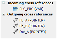
Cross references
Cross-references in the class diagram are dependencies and relationships between the elements of the diagram.
In the ToolBox view, in Incoming cross references and Outgoing cross references, elements are listed that have a relationship to the selected box element, but are not currently displayed in the diagram. For example, this is the case when the Delete from diagram command was used to remove an element from the class diagram but not the project. In Incoming cross references, missing incoming relationships with the source element are listed. In Outgoing cross references, missing outgoing relationships with the end element are listed.
You can drag a missing element from the ToolBox view to the class diagram.
If the selected element is a class with a relationship to a library function block, then this relationship is also detected and can be displayed as a missing element.
Click .
Select a box element in the class diagram that has relationships not represented in the class diagram.
The relationships are listed in the ToolBox view.
Drag an element listed in Incoming cross references or Outgoing cross references to the class diagram.
The element is displayed in the class diagram.
Refactoring
The following changes that are made in the class diagram editor can be applied easily to the entire project by means of refactoring:
Renaming variables, POUS, or properties
Adding and removing variables of the type
VAR_INPUT,VAR_OUTPUT, orVAR_INOUT
Tip
By default, the refactoring functionality and the associated preview () are enabled in the class diagram. However, you can restrict them using the options dialogs in Dialog: Options: Refactoring:
In particular, note that the preview dialog can be skipped in the options for the UML class diagram. In this case, the change will be applied throughout the project without any prompt.
For more information, see: Dialog: Options: UML