Testing the RIGHT Function and Detecting Errors
The example displays the test of the RIGHT string function in the Standard library. The test code is configured with a test table.
With test tables, you can test function blocks only. To test a function, implement a wrapper function block. You implement a function block which calls this function and maps the inputs and outputs of the function and passes this 1:1 to the function. If the wrapper function block is the testee, then the function is tested indirectly.
Creating a test project
Use the project wizard to create a new standard project
Project_RIGHTfor the available controller.The project is created with an application, the
PLC_PRGprogram, and a device.In the device tree, select the Application object.
Click .
Select the POU object.
The Add POU dialog opens.
Specify the name
FB_RIGHT.Select the Function block type and the Structured Text (ST) implementation language.
Click Add.
The function block is created.
Specify the following declaration in the
FB_RIGHTfunction block:VAR_INPUT strCompleteString : STRING(255); iSize: INT; END_VAR VAR_OUTPUT strResult : STRING (255); END_VAR
Specify the following implementation in the
FB_RIGHTfunction block:strResult := right(strCompleteString,iSize);
The testee is created. The wrapper function block calls the function to be tested. The inputs and outputs are routed through.
Creating a test table
In the device tree, select the Application object.
Click .
Select the Test Table object.
The Add Test Table dialog opens.
Specify the name
TestTable_RIGHT.Select a testee. Then click the
 button.
Select the POU
FB_RIGHT.Click the Scan Testee button.
A list opens with all inputs and outputs of the function block.
Activate all inputs and outputs.
The enabled variables are inserted automatically as columns in the test table on the Tabular Editor tab.
Click the Add button.
The test table is inserted below the application. The input and output assignments are missing.
Configuring a test table
Click the Tabular Editor tab.
Select the line <click here to create a test case> and specify the name
TC 1: empty string.Select the row <edit to create a test step> and specify the name
Test 1.Specify the following data in the test table:
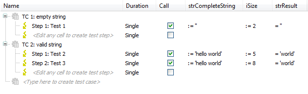
Test 1: The test step detects the last two characters of an empty string. The result is also an empty string. This test yields a positive result.
Test 2: The test step detects the last five characters of the string
'hello world'. The result is'world'. This test yields a positive result.Test 3: The test step detects the last eight characters of the string
'hello world'. The result is'lo world'. This test yields a negative result.
Executing an IEC unit test
Tip
The test run, which is created in the test script, always includes preparatory test actions before calling an IEC unit test. The ApplicationTest script, which is installed with the package, provides an example of this. The preparatory test actions are combined there in the Prepare test case.
Create a new test script.
Click .
The Test Manager view opens.
Select the Test Scripts entry and click .
A new test script is added.
Double-click the new test script.
The test script opens in the editor.
Select the test script in the editor and click .
An IEC unit test is added to the test script.
Insert the preparatory test actions before the IEC unit test (see example:
IecUnitTest).Check the connection settings and start the
Control Win V3controller.Click the Save + Run button.
The test script is executed.
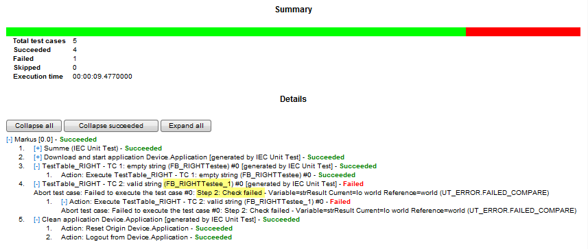
After the test script has been executed, the test report appears.
First the project is searched for test tables. The result is the
TestTable_RIGHTtest table. TheFB_RIGHTfunction block is entered in this test table as the testee.Then test POUs are instantiated for the testee. One test POU per test case: the
TestTable_RIGHTTesteetest POU for test case 1 and theTestTable_RIGHTTestee_1test POU for test case 2.The test POUs are used for checking parameters.
According to the input and output assignments in the test table, the test POUs
TestTable_RIGHTTesttable_RIGHTTC1Emptystring (FB)andTestTable_RIGHTTesttable_RIGHTTC1Validstring (FB)are instantiated for test cases 1 and 2. These function blocks execute the testee. Then the inputs are set and the outputs are checked for the result.
Important
Note the following before you run the test again: Delete the Backup application and remove the automatically inserted rows marked with comments in the PLC_PRG program.
Examine the testee with negative test results
The test report lists the result of the test run for each test step. If a test step is run with errors, then the expected and the actual value of the tested variable are listed in the report. After the test run, you can execute the generated test application and debug the error.
In the test report, a test POU with a failed check is marked in red as Failed. In this row, the name of the created test POU is also in this row (in the example TestTable_RightTestee_1).
Click .
Your system can communicate with the controller.
In the POU view, open the
FB_RIGHTTestee_1 (FB)function block.In the first line of the function block, set the cursor and press the F9 key.
A breakpoint is set.
Open the
PLC_PRGprogram in the editor.In the declaration part, expand the variable
instFB_RIGHTTESTTABLE_RIGHTTC2VALIDSTRING.Click in the Prepared Value field of the
xExecutevariable (in classETrigA).TRUEis displayed as the prepared value.Click (Ctrl + F7).
The variable is set (forced) to
TRUE.Click (F5) to start the program.
The program starts and processes until halting at the breakpoint in the
Test_RightTestee_1function block.Click .
The program flow skips to the FB
instFB_RIGHTTESTTABLE_RIGHTTC2VALIDSTRING.Now you can step through the function blocks and observe the input and output values.