Buffering and Blending of Movements
Movement commands can be buffered with CODESYS SoftMotion. For each commanded movement, it can be specified how the movement is buffered and how the blending should be performed from the preceding movement to the new movement. The commanded path is adjusted by rounding the corners so that the path can be traveled without stopping.
Whether or not a movement is buffered, and how it is done, can be configured by means of the BufferMode input of the movement block (for example, MC_MoveDirectAbsolute or MC_MoveCircularRelative). For more information, see the following: MC_Buffer_MODE.
The TransitionMode and TransitionParameter inputs determine how corners are rounded. For more information, see the following: MC_TRANSITION_MODE.
For more information about movements, see the following: Function Blocks for Movements
Note
In blending modes, the TransitionMode must not be equal to TMNone.
Tip
Blending between two movements starts at the earliest halfway through the first movement and ends at the latest halfway through the second movement.
If the first movement has already been planned too far, then blending may no longer be possible with the set parameters. Then the blending area is reduced or blending is not possible anymore. In order to guarantee a successful blending, both movements should be commanded in the same cycle.
Path dynamics when blending
If blending is performed between CP movements (between linear and circular segments), then it should be noted that the maximum path acceleration and the maximum path jerk may be exceeded during the blending. The shorter the blending range is, the more prominent this effect will be. However, the limits of the axes (the maximum axis acceleration and the maximum axis jerk) are always maintained.
Therefore, if the maximum path acceleration is low and the maximum axis acceleration is high, then accelerations which are too high can occur when blending. This can be counteracted by means of the AccFactor input of the motion blocks, for example, by reducing the maximum axis acceleration for a movement.
Features of TMStartVelocity
The calculation of the blending points is based on an idealized velocity curve, which can deviate from the actual velocity curve. At this time, a deceleration ramp is simulated on the original path towards the blending point and an acceleration ramp and away from the blending point. The minimum from both the programmed path velocity and the estimated maximum path velocity resulting from the axis limits is used as the target velocity.
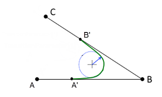
In addition, when blending between straight lines, the angle between them is taken into account. A minimum curvature radius for the blending element results from the desired path velocity and the estimated dynamics limits. The points A' and B' result in turn from this radius and the angle between the straight lines.
If the movements are slowed down during the blending process despite a set factor of 1, then increasing the factor may help.
Example
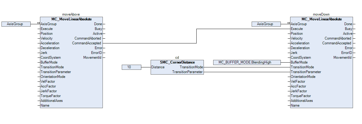
In a small example application, a workpiece is supposed to be picked up. The robot should first move above the workpiece and then downwards to pick it up. To reach the workpiece as fast as possible, travel between the two movements should not be stopped, but blended. Blending into the second movement should begin ten units before the end of the first movement is reached.
In order to meet the requirements, two movements must be commanded. The first movement (moveAbove) over the workpiece and the second movement (moveDown) downwards towards the workpiece. For the second movement, it must be defined how the movement should be buffered and blended.
As shown in the following image, BlendingHigh is selected for the BufferMode. This defines that the movement should be buffered after the first movement and then blended. In addition, for the TransitionMode, TMCornerDistance is defined with a distance of 10 units to smoothly blend the first movement into the second movement. In order to set the two inputs TransitionMode and TransitionParameter appropriately, the SMC_CornerDistance function block is used.