Position Control on the Controller with SM_Drive_PosControl
See the PosControl.project sample project in the installation directory of CODESYS under ..\CODESYS SoftMotion\Examples.
In most cases, a servo control takes over the position control of the drive, as well as the power control and rotational speed control. However, there are use cases in which the controller takes over the position control of the axis. This example demonstrates how a speed-controlled device (for example, frequency converter with position feedback) is position-controlled by CODESYS SoftMotion.
The requirement is a device that is controlled by the set velocity and returns its current position. In this example, a 10V analog output terminal EL4031 is used with a signal that is used as a speed setpoint for a frequency converter. An encoder terminal EL5101 is used for position feedback.
Control of the axis position by means of SM_Drive_PosControl
Add a position-controlled axis of type
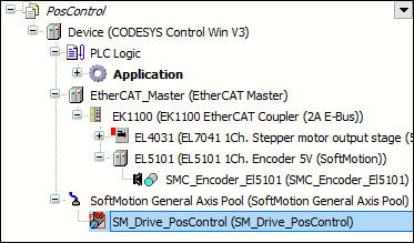
SM_Drive_PosControlbelow SoftMotion General Axis Pool in the device tree.Add the terminals for the analog terminal (EL4031) and the encoder (EL5101) to the device tree.
Device tree:
Tip
The device descriptions of the fieldbus devices have to be downloaded and installed from the manufacturer.
Open the
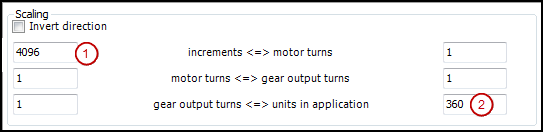
SM_Drive_PosControldevice in the editor and specify the general parameter Modulo with value360.0on the General tab.Click the Scaling/Mapping tab. The number of increments per motor turn is taken from the data sheet of the encoder. In this example,
4096increments (1) are one motor turn. Because you are working with angular degrees in the application, you specify the value360(2) for units in application.Settings:
Switch to the SoftMotion Drive: Position Control Loop tab and specify the following parameters:
D 2.0The dead time determines the number of cycles that the received actual position (encoder) is phase-shifted to the set position of the axis. The dead time depends on the applied components and has to be determined by trial and error.
Kp 0.0The constant of proportionality is the factor by which the position error (the deviation between set and actual position) is multiplied to be added later to the set velocity. Now set this value to
0. You will determine the value experimentally at a later time.Bit width: 16The bit width of the actual value is received depending on the used components and can be set as 16, 24, or 32-bit values. Set the value to
16because the used components yield the position asUINT.
maxLeave the position error monitoring switch off. You can switch it back on again if necessary. Select the check box and specify a maximum permitted lag. If this value is exceeded during operation, then the axis goes into an error state.
δ/δtThe parameter has the value 1 and should be changed only in very special cases. It defines the relationship between the set velocity and the derivation of the position. The value range is 0 to 1:
0: Only the numerical derivative offSetPositionis used.1: OnlyfSetVelocityis used.
Control loop:

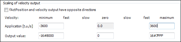
Now you set the velocity values that are sent to the actuator. For this purpose, you need to know the maximum velocity in application units and the corresponding raw value of the transferred data. In this example, the maximum velocity is achieved by the output of the value
16#7FFF, which corresponds to a velocity of 10 turns per second. This also corresponds to 3600 degrees per second according to the settings.Settings:
Mapping of variables to inputs and outputs
Map the variables with the axis data to the I/O modules. The available cyclic data of the axis are located in the data structures in and out. You can establish this connection in the device editor of the input and output device either programmatically or directly.
Connect the output (set speed) to the EL4031 device. Open the device in the editor and click the EtherCAT I/O Mapping tab. Assign the variable
out.iSetVelocityof the axis to the output. In the case of a 32-bit output,out.diSetVelocityis used.Mapping:

Proceed in the same way with the position input. Open the EL5101 device in the editor and set the position input value to
in.wActPosition. For a 32-bit input, set the value toin.dwActPosition. Mapping: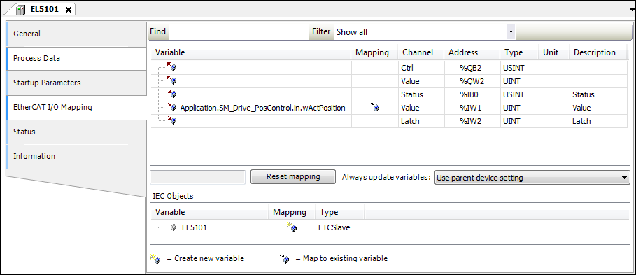
In order for control enable, quickstop, and limit switch to operate, the corresponding inputs of
SMC_PosControlInputhave to be defined by the values of the drive. The outputs ofSMC_PosControlOutputhave to be transmitted to the drive (see description below). If the drive does not support quickstop, for example, thenSM_Drive_PosControl.in.bDriveStartRealState := TRUEhas to be set andSM_Drive_PosControl.out.bDriveStartcan be ignored. In this example,bDriveStartRealStateandbRegulatorRealStatehave to be set in the application.
SM_Drive_PosControl.in.bDriveStartRealState := TRUE;
SM_Drive_PosControl.in.bRegulatorRealState := TRUE;
Determining the dead time of the system
Now set online mode with the axis and set the control parameters.
Important
Note that the axis may move out of control. Therefore you need to take corresponding safety precautions.
Then try to operate the axis without position control.fKp is already set to 0.0 and the scaling settings are verified. Switch the axis to MC_Power and start MC_MoveVelocity. The axis now moves at the programmed velocity of 1 U/s. In case of deviations, you will have to correct the scaling accordingly.
End the movement, for example with
MC_MoveRelative, and start the trace function.Determine the dead time of the system by measuring the time difference between the set position and the actual position.
In
MC_MoveRelative, set the maximum velocity and a large acceleration. Start the sampling trace withMC_MoveRelative. Now determine the time difference between the start movement of the set position and the first reaction of the actual position.Trace:

To determine the dead time
D, divide this time difference by the cycle time (D = time difference / cycle time). On the SoftMotion Drive: Position Control tab, specify this value in control loop atD.Now try to determine the correct setting for
fKp. To do this, change the value of the variable<drive>.controller.fKpin a watch list.Set
fKpto a small number (e.g., 0.0001) and increase the value step by step. Check the behavior for each change with the sampling trace. As soon as you detect fluctuations, the upper limit has been reached. Now decrease the value offKpby about 10% and specify it on the SoftMotion Drive: Position Control tab in the control loop atKp.Now you can use the axis.
Function Block: SMC_PosControlInput
Library: SM3_Drive_PosControl
Name | Data Type | Initial Value | Description |
|---|---|---|---|
|
| Limit switch in positive direction (for finite axes only) Since SoftMotion version 4.12.0.0, the limit switch monitoring is enabled by default. For older versions, this has to be enabled manually by setting
| |
|
| Limit switch in negative direction
| |
|
| Current position (actual position) as 16-bit value | |
|
| Current position (actual position) as 32-bit value | |
|
| External error | |
|
|
| |
|
|
| |
|
|
| |
|
|
Use case: The value is held at |
Function Block: SMC_PosControlOutput
Library: SM3_Drive_PosControl
Name | Data Type | Initial Value | Description |
|---|---|---|---|
|
|
| |
|
|
| |
|
| Set velocity | |
|
| Set velocity |
Function Block: SMC_SetPosControlParams
Library: SM3_Drive_PosControl
Changes the parameters of an SM3_Drive_PosControl axis
Name | Data Type | Initial Value | Description |
|---|---|---|---|
|
| Axis reference | |
|
|
| |
|
| -1 | Proportional gain for lag A value less than 0 is ignored. |
|
| -1 | Factor for the velocity control with 0: No velocity pilot control; 1: Direct output of |
|
| -1 | Time lag in cycles between This value must not be 0. A value less than 0 is ignored. |
|
| -1 | Maximum position lag 0 deactivates the check of the maximum position lag. A value less than 0 is ignored. |
Name | Data Type | Initial Value | Description |
|---|---|---|---|
|
| The execution of the function block has been ended. | |
|
|
| |
|
| Error identification |
The parameters of the axis drive SM_Drive_PosControl are set.
PROGRAM PLC_PRG
VAR
        fbSetPosControlParams : SMC_SetPosControlParams;
END_VAR

fbSetPosControlParams.fKp := 1;
fbSetPosControlParams.fPartVelPilotControl :=0;
fbSetPosControlParams.fDeadTime :=0.1;
fbSetPosControlParams.fMaxPositionDiff :=1;

fbSetPosControlParams(Axis:= SM_Drive_PosControl, bExecute:= TRUE);