CNC Example 08: Use of Additional Axes
See the CNC08_AdditionalAxes.project sample project in the installation directory of CODESYS under ..\CODESYS SoftMotion\Examples.
This example extends the CNC01_direct.projekt project which is described in CNC Example 01: Generating OutQueue Directly. It demonstrates how to use additional axes. As in CNC Example 01, four positions are approached in the X/Y-plane with a defined velocity and acceleration. Furthermore, the additional axis A is run during each movement. The program sets two path switch points on the path.
Editing a CNC program in the editor
Open the
CNC01_direct.projectproject from the installation directory of CODESYS.In the project, open the CNC program
Example.Add positions for the additional axis A to the travel commands:
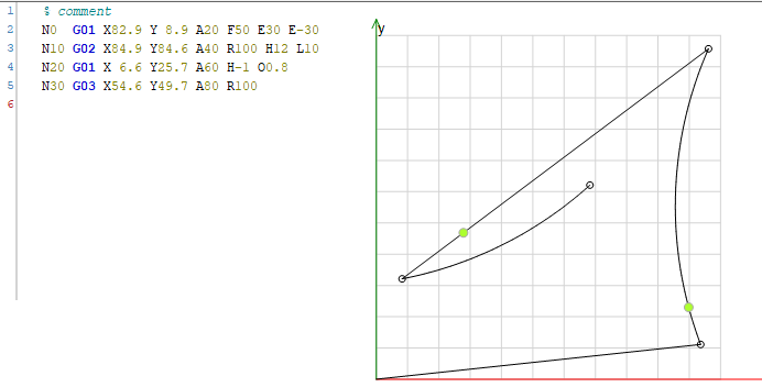
Example 49. CNC editorN0 G01 X82.9 Y 8.9 A20 F50 E30 E-30 N10 G02 X84.9 Y84.6 A40 R100 H12 L10 N20 G01 X 6.6 Y25.7 A60 H-1 O0.8 N30 G03 X54.6 Y49.7 A80 R100
Creating a drive interface and PLC configuration
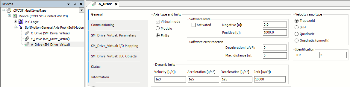
Insert an additional virtual drive A_Drive below the SoftMotion general axis pool.
Set the parameters as follows:
Editing an IEC program
Open the CFC program
Ipo.Activate the previously added drive A_Drive with the
MC_Powerfunction block.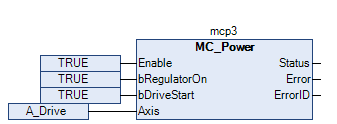
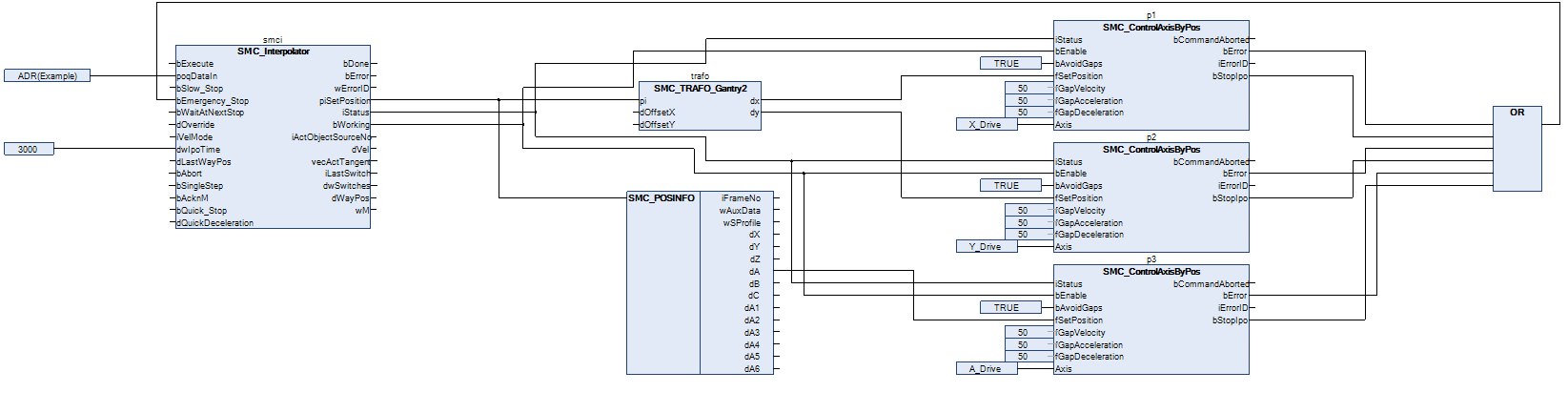
In this example, a simple orientation axis (A_Drive) should be controlled with the additional axis A. For this reason, no more transformation modules are necessary. The set position of the interpolator corresponds directly to the set position of the drive and is applied via the
SMC_POSINFOselector with theSMC_ControlAxisByPosfunction block. The application does not guarantee that the outputs of the interpolator are continuous. For example, the position of the additional axis ends at a different point than it begins. Therefore, you should activate the gap avoidance (bAvoidGaps,fGapVelocity,fGapAcceleration, andfGapDeceleration). Then connect thebStopIpooutput to thebEmergency_Stopinput of the interpolator and connect interpolator outputiStatusto the respective inputs of the axis control function blocks.Above all, pay attention to the correct order of function blocks when programming with CFC.
Commissioning
Compile and start the created program. The program executes the CNC motion as soon as the Execute input of the interpolator has been set. After the program has run completely, you can apply a new rising edge to restart it.
During the execution of the CNC program, note the position of the additional axis A (piSetPosition.dA) which is shown in the visualization of the interpolation POU.