Coordinate Systems
CODESYS SoftMotion Robotics provides different coordinate systems in which movements can be commanded.
Axis Coordinate System (ACS)
Tool Coordinate System (TCS)
World Coordinate System (WCS)
Machine Coordinate System (MCS)
Product Coordinate System (PCS_1, PCS_2)
Coordinate System | Description |
|---|---|
Axis Coordinate System (ACS) | The axis coordinate system defines a coordinate system in axis space where each axis of the robot spans one dimension. As a result, a position can be specified for each axis of the robot. |
Tool Coordinate System (TCS) | The tool coordinate system is a Cartesian coordinate system which lies on the tool center point (TCP) of the kinematics. Its position and orientation depend on the position of the robot. |
World Coordinate System (WCS) | The world coordinate system is a static Cartesian coordinate system and forms the basis for all subsequent coordinate systems. These are defined relative to the world coordinate system. |
Machine Coordinate System (MCS) | The machine coordinate system is a static Cartesian coordinate system. The position and orientation of the MCS relative to the physical robot are defined by the kinematics. The MC_SetCoordinateTransform function block can be used to shift the coordinate system relative to the world coordinate system (WCS). |
Product Coordinate System (PCS_1, PCS_2) | The product coordinate systems are Cartesian coordinate systems which can be defined by the user. They are expressed relative to the world coordinate system (WCS) and can be either static or dynamic. . Static
. Dynamic The following function blocks can be used to define dynamic coordinate systems: |
Initial position and orientation of the coordinate systems
The kinematics of the robot determine the initial position and orientation of the coordinate systems. This is described in the documentation of the kinematics.
Position and orientation of the machine coordinate system (MCS) relative to the physical robot
Position and orientation of the tool center point (TCP) relative to the MCS and therefore the tool coordinate system (TCS)
Zero position of the robot as well as the directions of rotation or movement of the individual axes
The world coordinate system (WCS) and the product coordinate systems (PCS_1, PCS_2) are not initially shifted and are identical to the machine coordinate system.
Multiple robots and workpieces
The position and orientation of the coordinate systems are defined for each robot. When multiple robots are working together, it can be useful to define the world coordinate system (WCS) as a common base coordinate system. Based on this coordinate system, the machine coordinate systems (MCS) and product coordinate systems (PCS_1, PCS_2) of the individual robots can be shifted.
Example
Example using a robot with two rotary joints (a0 and a1)
Kinematics
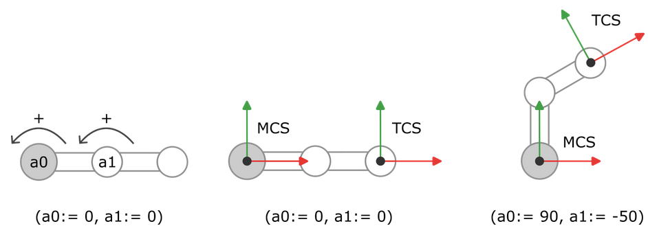
The kinematics define the zero position of the robot (as shown below). The origin of the machine coordinate system lies on the axis of rotation of axis a0. The X-axis points in the direction of the first link when the position of the first axis a0 is 0. The Y-axis points in the direction of the first link when the position of the first axis a0 is +90°. Counterclockwise rotation corresponds to the positive direction of rotation. The tool center point (TCP) lies at the end of the second link of the robot (as shown below) and forms the origin of the TCS. The TCS is aligned in such a way that the X-axis runs along the second link.
Axis Coordinate System (ACS)
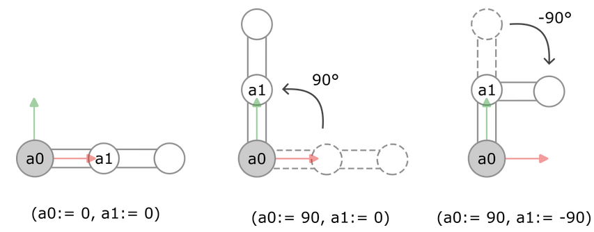
The kinematics have specified the zero position of the robot and the direction of rotation of the individual axes. Because the robot consists of two axes a0 and a1, we can specify the positions of axes a0 and a1 in the ACS.
In the first image, we specify the position (a0:= 0, a1:= 0). This corresponds to the zero position of the robot.
In the second image, we specify the position (a0:= 90, a1:= 0). Starting from the zero position, the first axis a0 is rotated 90° in the positive direction of rotation. The second axis a1 remains in the zero position.
In the third image, we specify the position (a0:= 90, a1:= -90). Starting from the zero position, the first axis a0 is rotated 90° in the positive direction of rotation (as in the second image). In addition, the second axis a1 is rotated 90° in the negative direction of rotation.
Tool Coordinate System (TCS)
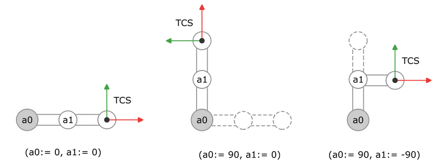
The kinematics define the position and orientation of the TCP and TCS. Depending on how we move the robot, the position and orientation of the TCS also changes.
World Coordinate System (WCS), Machine Coordinate System (MCS), and Product Coordinate System (PCS_1, PCS_2)
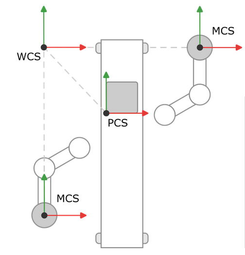
In a production hall, two robots stand to the left and right of a conveyor belt. The robots should process products on the conveyor belt. We define a common world coordinate system and place it in the top left-hand corner of our production hall. Starting from this coordinate system, we determine the distance and rotation to the machine coordinate systems and the product and shift the coordinate systems accordingly.
In the example, all coordinate systems are aligned in the same way so that we only need to shift the coordinate systems. The machine coordinate system of the left robot is shifted in the Y-direction, the machine coordinate system of the right robot is shifted in the X-direction, and the product coordinate system is shifted in both the X-direction and Y-direction.