CNC Editor Fundamentals
With DIN 66025, you can create up to 9-dimensional paths. Three of these dimensions are not interpolated linearly. In X/Y/Z, you can program lines, arcs, ellipses, parabolas, and splines. Another eight additional axes are provided. Of these, five are interpolated linearly (P/Q/U/V/W) and three with a 3rd degree polynomial (A/B/C). For each motion block in the CNC program, the interpolator computes the traverse path. At the same time, the interpolator computes the shape of the path, velocity, acceleration, and jerk according to the specified interpolation. For each programmed path, CODESYS creates a global data structure automatically with the CNC data that can be used in an IEC program.
There are different options for this purpose:
SMC_CNC_REF: The CNC program is saved as an array of G code words that are processed at application runtime by means ofSMC_NCInterpreter. The result is the CNC path described as a sequence of GEOINFO structure objects. By means of path preprocessing modules from the SM3_CNC library (example: tool radius correction), these objects can be edited, interpolated, transformed, and transferred from the drive interface to the hardware for communication.SMC_OUTQUEUE: The CNC program is written to a data structure as a list of GEOINFO structure objects with the nameSMC_OUTQUEUE, and it can then be input directly into the interpolator. As a result, in contrast toSMC_CNC_REF, the interpreter function block and the path preprocessing function blocks do not have to be called. However, the program cannot be changed at runtime and no variables in G code can be used in this mode.FILE: Then the CNC program is saved as an ASCII file in the file system of the controller and read and implemented step by step. This method is appropriate especially for large programs that cannot be stored entirely in the memory. It is also appropriate for programs that were generated by the user after compiling the controller application.
Structure of the CNC editor
The CNC editor consists of the following components:
Main editor: The text editor shows the DIN 66025 program, or the tabular editor shows the CNC path.
Graphical editor: The graphical view of the path is shown here.
Properties view of the CNC elements
Toolbox view: Contains tools for selecting and inserting path elements
When you press the F6 key, the focus toggles between the main editor and the graphical editor. If a path element is selected in the graphical editor, then the respective motion block or line is selected implicitly in the text editor or tabular editor. Likewise, an element selected in the tabular editor or text editor is also selected in the graphical editor. Changes in the graphical editor are applied in the text editor or tabular editor, and the other way around.
Tip
Application-wide CNC settings are applied and saved in the CNC Settings object.
Object-specific CNC settings are applied and saved in the Properties dialog of the CNC object.
SoftMotion software components of the CNC editor
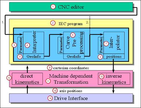
(1) CNC editor | (2) IEC program | (3) Parameter |
(4) Interpreter | (5) GeoInfo | (6) Path preprocessing |
(7) Interpolator | (8) Path points | (9) Cartesian coordinates |
(10) Direct kinematics | (11) Machine-specific transformation | (12) Inverse kinematics |
(13) Axis position | (14) Drive interface |
Compiling CNC objects
The Compile mode is selected when adding a new CNC object, and if necessary it can be changed in the Properties dialog (CNC tab of the CNC object). Depending on the Compile mode, a SMC_OutQueue function block, SMC_CNC_REF function block, or an ASCII file with the programmed CNC path is created at compile time.
If the Exclude from build option is selected in the Properties dialog on the Build tab of the CNC object, then no IEC data is generated. In compile mode File, no data is downloaded to the controller.
Opening a CoDeSys V2.3 Projects
When you open a CoDeSys V2.3 project in CODESYS, a converter is provided to execute the following functions as long as a SoftMotion controller is used:
Every CNC program is converted into a CNC object with the same name and implementation type DIN 66025. The compile mode, the queue size, and the start position of the converted program are also applied as the status of the step suppression.
If the Exclude from build option is selected in the CNC program of the CoDeSys V2.3 project, then this option is accepted.
The CNC settings object is generated automatically.
All CNC objects are listed below a SoftMotion-capable application.