Shifting, Rotating, and Scaling the Coordinate System
G code: G53, G54, G55, G56
Function:
The G code commands G54, G55, and G56 shift, rotate, and scale the decoder coordinate system which is used internally by the interpreter function block SMC_NCInterpreter. The coordinate transformations are calculated for all path elements during the execution of the SMC_NCInterpreter function block instance.
The G code command G53 resets the decoder coordinate system to the original position, orientation, and scaling (corresponding to the machine coordinate system).
Tip
You shift and rotate the decoder coordinate system in order to reuse the G code of the same path elements that differ only by position, orientation, or scaling.
Tip
Rotating and scaling the decoder coordinate system only works in the online interpreter (not in the CNC editor).
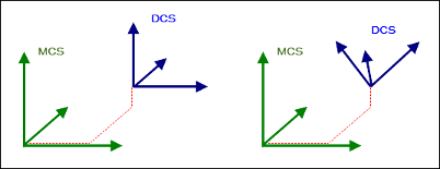
MCS and DCS coordinate systems
The machine coordinate system (MCS) is defined by the applied kinematics which determine its position and orientation.
The decoder coordinate system (DCS) is managed by the interpreter (SMC_NCInterpreter function block instance). All coordinate information for motion commands are interpreted in this coordinate system. This affects the target position of a movement (X/Y/Z), as well as an arc midpoint (I/J/K) or a plane that is set with G15/G16/G17/G18/G19.
The DCS is programmed with the commands G53/G54/G55/G56. You can rotate, shift, and scale the DCS with respect to the machine coordinate system, and therefore adapt the position, orientation, and scaling in the G code file any number of times. You program the path elements relative to the DCS. For example, this can be an advantage for the same path elements in different positions and orientations.
The following image shows a shift (left) and a shift with rotation (right).
The interpreter gets the information from its eOriConv input about whether A/B/C are treated as additional axes or as orientation values. The coordinates of the path elements are transformed accordingly. Therefore, the interpreter function block manages an active coordinate system. Initially, if the DCS is neither shifted, nor rotated, nor scaled, then the DCS corresponds to the MCS. The start and target positions and the plane for arcs are specified in the generated GeoInfo objects always relative to the MCS.
| No orientation convention is specified. The contents of the G code word A/B/C is interpreted as an shift value. |
| The orientation convention is the standard Y convention (Z, Y', Z''). The contents of the G code word A/B/C is interpreted as an angle value. |
| The orientation convention is the yaw-pitch-roll convention (Z, Y', X''). The contents of the G code word A/B/C is interpreted as an angle value. |
| The orientation convention is the XYZ convention (X, Y', Z''). The contents of the G code word A/B/C is interpreted as an angle value. |
Commands G53, G54, G55, G56
G Code | Description |
|---|---|
| Resets the decoder coordinate system The DCS is reset to the same position and orientation as the MCS. |
| Absolute shift, rotation, and scaling of the DCS The values refer to the MCS. If an orientation convention is not specified ( If an orientation convention is specified, then the command results in a shift also along the axes X/Y/Z and along the additional linear axes P/Q/U/V/W. In addition, the coordinate axes are rotated. Then the orientation convention provides the rotation order and the G code words A/B/C give the angles of rotation in degrees. Note: The decoder can perform directional rotations in a range from -180° to +180°. If you specify an angle outside this range, then the decoder converts the value so that it is within the executable range. Only then does the decoder rotate the coordinate axes. For example, a rotation of -10° is performed for an angle of 350°. |
| Relative shift, rotation, and scaling of the DCS to its current position and orientation Therefore the values are relative to the current DCS origin and interpreted in the direction of the current coordinate axes of the DCS. An additional shift/rotation is added with respect to the machine coordinate system. If an orientation convention is not specified, then the command results in a relative shift only along the axes X/Y/Z/A/B/C and on all additional linear axes P/Q/U/V/W. Therefore, a shift can also be programmed along the A/B/C axes. If an orientation convention is specified, then the command results in a relative shift also along the axes X/Y/Z and along the additional linear axes P/Q/U/V/W. But above all, the coordinate axes are rotated further. Then the orientation convention provides the rotation order and the G code words A/B/C give the angles of rotation. |
| Resets the reference point of the decoder coordinate system The current orientation, position, and scaling of the DCS is set as a reference. Hint: If the reference point is X0 Y0 Z0 A0 B0 C0, then the DCS is set identically to the current position and orientation. |
Syntax
G53
G54 X Y Z A B C I J K P Q U V W
G55 X Y Z A B C I J K P Q U V W
G56 X Y Z A B C I J K P Q U V W
G Code Word | Description |
|---|---|
| Value around which the decoder coordinate system is shifted |
| If the input is If the Note: When programming the DCS rotation, the angles of rotation should always be specified in |
| Scaling in direction X Example: |
| Scaling in direction Y Example: |
| Scaling in direction Z Example: |
| Value around which the additional axis of the decoder coordinate system is shifted |
Shifting the DCS
Set the
eOriConvinput of theSMC_NCInterpreterfunction block instance toSMC_ORI_CONVENTION.ADDAXES.The DCS can be shifted. A rotation is not possible.
Program the CNC path. First, specify the position shift of the DCS.
Example:
G54 X10 Y10 Z10 A30 B30 C30The X/Y/Z/A/B/C axes of the DCS are shifted.
Absolute offset
N10 G0 X100 Y100 F100
N20 G54 X50 Y50    (Offset auf 50/50)
N30 G1 X0 Y0       (Fahrt nach 50/50)
N40 G54 X100 Y100  (Offset auf 100/100)
N50 G1 X0 Y0       (Fahrt nach 100/100)
N60 G53            (Offset auf 0)
N70 G1 X0 Y0       (Fahrt nach 0/0)
Current position as offset
N0 G0 X100 Y100 F100
N10 G56 X0 Y0  (Aktuelle Position 100/100 wird 0/0)
N20 G1 X10     (Fahrt nach 110/100)
N30 G56 X20 Y0 (Aktuelle Position 110/100 wird 20/0)
N40 G1 X0      (Fahrt nach 90/100)
Adapt offset by value
N0  G54 X10 Y20 Z30  U7 (Offset: X=10, Y=20, Z=30, U=7)
N10 G55 X-10 U7         (Offset: X=0, Y=20, Z=30, U=14)
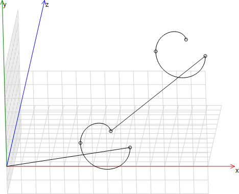
Same path elements in two positions
N05 G17
N10 G54 X10 Y10 Z10
N20 G01 X6.574 Y-10 Z-1.961 I8.287 J-0.000
N30 G02 X-0.480 Y-10 Z0.008 I-3.527 J4.988E-05
N040 G02 X3.418 Y-9.806 Z4.482 I1.949 J0.097
N50 G55 X10 Y10 Z10
N60 G01 X6.574 Y-10 Z-1.961 I8.287 J-0.000
N70 G02 X-0.480 Y-10 Z0.008 I-3.527 J4.988E-05
N80 G02 X3.418 Y-9.806 Z4.482 I1.949 J0.097
Shifting and rotating the DCS
Set the
eOriConvinput of theSMC_NCInterpreterfunction block instance to the desired orientation convention (for example,SMC_ORI_CONVENTION.ZYZ).The orientation convention and the rotation order of the X/Y/Z axes of the DCS are programmed. For
SMC_ORI_CONVENTION.ZYZ, the rotation order is ZY'Z'' and corresponds to the standard Y-convention.Note: As long as the
eOriConvinput contains an orientation convention and not the valueSMC_ORI_CONVENTION.ADDAXES, the values of the wordsA/B/Care interpreted as angle values for the rotation for the G code commandsG54/G55/G56.Program the CNC path. First, specify the position shift and rotation of the DCS.
Example:
G54 X10 Y10 Z10 A30 B30 C30The values of the words
A/B/Cprovide the direction of rotation and the angle in degrees. The coordinate system is rotated accordingly. The values of the wordsX/Y/Zdefine the shift.Note: When programming the DCS rotation, the angles of rotation should always be specified in
A/B/Cfor all three axes. A missing angle of rotation causes an error when decoding (SMC_DEC_DCS_NOT_ALL_OF_ABC_GIVEN).If the
eOriConvinput of theSMC_NCInterpreterfunction block instance contains the valueSMC_ORI_CONVENTION.ADDAXES, then rotating the DCS is not possible. The values inG54/G55/G56are interpreted as additional spline axis values. Shifting is possible.
The orientation convention was defined in the examples as the standard Y-convention (eOriConv = SMC_ORI_CONVENTION.ZYZ). In general for G54: X/Y/Z/A/B/C/P/Q/V/W provides an absolute value in the MCS. G55: X/Y/Z/A/B/C/P/Q/V/W provides a relative value in the DCS. G56: X/Y/Z/A/B/C/P/Q/V/W provides an absolute new value in the DCS.
Absolute orientation with G54
N01 G54 X10 A30 B0 C0
G54 results in a shift and rotation. The position and orientation are provided absolute to the MCS.
Relative orientation with G55
N01 G54 X10 A30 B0 C0 (Bezieht sich auf MCS)
N02 G55 Y10 A0 B30 C0 (Bezieht sich auf das in 01 definierte DCS)
G54 results in a shift of 10 units in the X-direction and a 30° rotation about the Z-axis absolute to the MCS. In block 02, the DCS is shifted an additional 10 units in the direction of the rotated Y-axis and then rotated an additional 30° about the rotated Y-axis. Therefore, the transformation in block 02 is relative to the transformation in block 01.
Referencing with respect to the current orientation with G56
N01 G01 X10 A10 B90 C10 (Orientierung ist A=10°, B=90°, C=10°)
N02 G56 A0 B0 C0        (DCS wird auf X=10, A=10°, B=90°, C=10° gesetzt)
G56 results in the current orientation of the DCS (programmed in block 01 in the example) to be set as a reference.
Example: Arc
N0 G17
N0 G54 A0 B90 C0
The selected circular plane is interpreted relative to the DCS. In the example, the X/Y-plane is selected with G17 and then the DCS is rotated 90° about the Y-axis. Then the selected plane in the DCS is the X/Y-plane as before. This corresponds to that of the X/Z-plane in the MCS.
With G17, the X/Y-plane is selected. Then the DCS is rotated by 90°. This results in the X/Y-plane being activated in the DCS as before. This corresponds to the X/Y-plane in the MCS.
Tip
In 2.5D mode (G15), rotation is permitted about the Z-axis only. Rotation about another axis causes an error which is issued by the decoder (SMC_DEC_DCS_2D_NOT_IN_XY_PLANE). Therefore, the X/Y-plane of the MCS always remains set in 2.5D mode.
Scaling the coordinate system
Important
If a rotation is programmed after an unequal scaling, then clipping can occur. In this case, the SMC_DEC_ROTATION_AFFECTS_SCALING error is not issued.
Important
All three scaling factors have to be specified or none at all.
Absolute scaling
Syntax: G54 I<i> J<j> K<k>
A coordinate system can be stretched or compressed in the three spatial directions X/Y/Z independently of each other. You can specify a factor for each direction. Specify the scaling factor for X in I, Y in J, and Z in K. A scaling factor > 1 extends. A scaling factor < 1 compresses.
Extending by 10x:
N01 G01 X10
N02 G54 A90 B0 C0 I10 J1 K1
N03 G01 X10 Y20
N04 G01 X5 Y10
All target points are extended by 10x in the direction of the rotated X-axis.
The following code generates the same path:
N01 G01 X10
N02 G01 X-20 Y100
N03 G01 X-10 Y50.
If neither I nor J nor K are specified, then the previously set value remains unchanged:
N01 G54 I10 J1 K1
N02 G54 X1
N03 G01 X10
The same path is achieved with the following code:
N01 G01 X101
Relative scaling
Syntax: G55 I<i> J<j> K<k>
A scaling factor > 1 extends. A scaling factor < 1 compresses. The scaling factors are multiplied.
Extending by 100x:
N01 G54 I10 J1 K1
N02 G55 I10 J1 K1
N03 G01 X10 Y20
N04 G01 X5 Y10
The following code results in the same scaling:
N01 G55 I100 J1 K1
Circular scaling
The scaling of an arc is valid only if the element is still an arc (not an ellipse) after the scaling.
When all three scaling factors are the same value
When the circular plane is one of the primary planes of the DCS and the corresponding two scale factors are the same values
Mirroring the coordinate system
An absolute scaling with negative scaling factors in I, J, or K results in mirroring of the current coordinate system.
Negative scale factor
G54 A30 B0 C0 I-1 J1 K1