Command: Analyze Dynamics
Function: The command starts a dynamics analysis of the CNC path active in the editor. At the same time, the dimensions for position, velocity, acceleration, and jerk of the CNC path are determined depending on the time, and they are displayed in the time charts of the Dynamics Analysis dialog.
Call: menu
Requirement: A CNC path is open in the editor.
Tip
In order to perform a dynamics analysis of the CNC path, there must not be any errors in the calculation of their path preprocessing.
For more information, see: Show preprocessed Path
Dialog: Dynamics Analysis
Tip
The settings in the dialog are used exclusively for displaying the dynamics analysis and have no effect on the CNC program or CNC settings.
In the dynamics analysis, the time curves for the dimensions of position, velocity, acceleration, and jerk are determined for the entire path that is traveled. The time charts are shown in the dialog on the same time axis. The settings of the dialog are used (preset or saved).
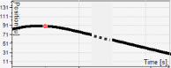 | Position curve of the selected axis (black) |
 | Red circle; indicates the beginning of a path element The tooltip of the marker provides information about the line numbers in the respective G code or in the table. |
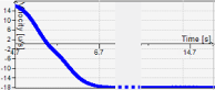 | Velocity curve of the selected axis (blue) |
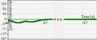 | Acceleration curve of the selected axis (green) |
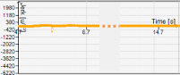 | Jerk curve of the selected axis (orange) |
The settings are saved when closed and used the next time the dialog is opened. For example, the zoom factor make only part of the curve visible. | |
 | Zooms into one part of the time curves Alternative:
|
 | Zooms out of time curves Alternative:
|
 | Zooms into the time curves so that the entire CNC paths are displayed |
Axis | Selection of axes: Preset: Path axis: Display of path position, path velocity, path acceleration, and path jerk |
Cycle time [µs] | Value for the Preset: Value Cycle time [µs] in object CNC settings (tab Preinterpolation) |
Velocity mode | Value for the |
Trapezoid | Trapezoidal velocity profile |
Sigmoid | Like Trapezoid, but rising or falling edges are replaced by sin² functions of the same surface. In this velocity mode, the limiting value is exceeded by approximately a factor of π/2. |
Sigmoid limited | Like Sigmoid, but the duration for interpolating the path is the same length as in the velocity mode Trapezoid. Default |
Quadratic | Acceleration profile in trapezoidal form with jerk limitation The jerk reaches a maximum value in Maximum jerk [u/s³]. This results in a quadratic velocity profile. The position profile consists of third-degree polynomials. The result is that the velocity profile consists of parabolas, the acceleration consists of linear segments, and the jerk consists of horizontal line segments. |
Maximum jerk [u/s³] | Jerk limitation |