How to change the cam path
These instructions use the example from the How to create a cam chapter to demonstrate how to change a cam.
Changing the path with the graphical editor
Open the Rotary table cam in the editor.
The Cam tab is visible.
Select the point at 120 and delete it by pressing the delete key (Del). Also delete the point at 240.
Select the Add point tool from the Toolbox view.
The mouse pointer turns into cross hairs when you move it into the editor.
Click near Master position 400 and Slave position 45 in the upper graphs (slave position).
The curve of the slave position is changed. The curves of velocity, acceleration, and jerk also change.
Select the new inserted point by clicking it.
Drag the point to another position.
The curve of the slave position is adjusted accordingly.
Change the X and Y properties to the exact values of 400 and 45, respectively.
In the same way, change the X-value to 45 of the point at master position 2000.
Select the Select tool from the Toolbox view.
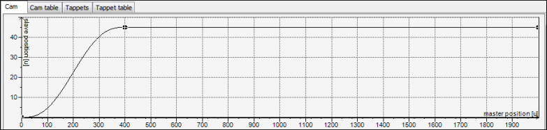
Select the second curve element (between 400 and 2000).
Change the Segment type property to Line.
Check the curve in the graphical editor.
Representation:
Changing the path with a cam table
Open the Vertical axis cam in the editor.
The Cam tab is visible.
Select the Cam table tab.
Click the
 symbol to delete the point at 120. Also delete the point at 240.
Click the
 symbol.
A new point and a new segment are inserted at (1000/150).
Add two more points.
Change the values X / Y of the following points:
Point 1:
0 / 0Point 2:
400 / 0Point 3:
600 / 250Point 4:
1800 / 250Point 5:
2000 / 0
The curve of the slave position is changed. The curves of velocity, acceleration, and jerk also change.
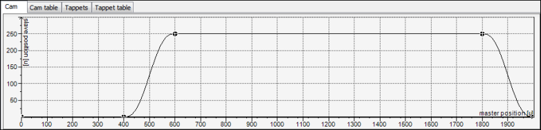
In the cam table, change the Segment type of the first and third segments to Line.
Check the curve in the graphical editor.
Representation:
Tip
In practice, the curves of the different cams are defined frequently as overlapping in order to save on cycle time. In the example above, the vertical axis could already begin the movement while the rotary table is still in motion (for example, at X: 350).