Electronic Gears, Phase Offset, and Compensation of Gear Backlash
See the BasicMotion_SynchronizedMotion.project example in the installation directory of CODESYS under ..\CODESYS SoftMotion\Examples.
This example shows how to use an electronic gearbox in combination with a phase offset and gear backlash compensation.
Structure of the application
The application consists of a simple state machine in the PLC_PRG program and a trace which you can use to easily track the functionality of the function blocks.
Enable the axes with
MC_Power.(STATE_POWER)Start the synchronous movements and move the master axis continuously between position 0 and position 100 (
STATE_COMMAND_POS_0andSTATE_COMMAND_POS_1).
Usage
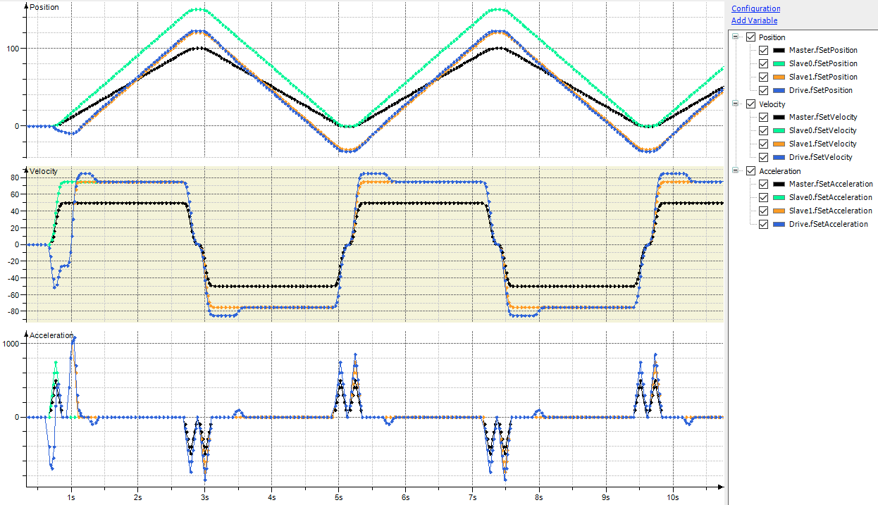
The master axis (black in the trace diagram) moves continuously back and forth between position 0 and position 100 at a maximum velocity of 50 units per second.
An electronic gearbox (MC_GearIn) with a gear ratio of 2:3 converts the master movement to the Slave0 axis (green in the trace diagram). The maximum velocity resulting from the gears is 75 units per second.
Then, a phase offset (MC_Phasing) of 30 units is applied to the Slave1 axis (orange in the trace diagram). The velocity is identical to the Slave0 axis, except for the ramp-in phase.
Finally, gear backlash compensation is used to bring the movement to the Drive axis (blue in the trace diagram). An unrealistically high value of 5 units is set for the gear backlash for demonstrative purposes. The diagram shows a compensating movement at the start of the movement and at each reversal of the direction of movement.