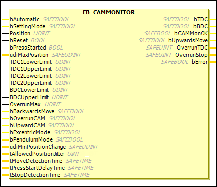
FB_CAMMONITOR
Description Function Block
The FB_CAMMONITOR function block is used to implement an electronic cam group. In addition to excentric mode, pendulum mode is also supported.
Excentric mode:
Only one direction of rotation is permitted in excentric mode.
A check is performed to make sure that the position stops after one cycle at the latest after the upper reversal point (TDC: Top Dead Center) plus maximum overrun (
OverrunMax).OverrunTDCoutputs the current overrun or the current position after TDC.The lower reversal point (BDC: Bottom Dead Center) is specified with a lower and upper limit. After the BDC is exceeded, the press is in upward movement. This information is output at the
bUpwardsMoveoutput.If the press comes to a standstill without having reached or exceeded TDC again or if the direction of rotation is reversed, then the
bCamMonOKoutput is immediately set toFALSE.After standstill is reached, a new cycle is permitted only after a falling edge is detected at the
bResetinput.The
bBackwardsMoveinput is used to notify the function block that a backward movement of the press is permitted. This is permitted only if the position is betweenTDC1UpperLimitandBDCLowerLimit. The backward movement ends whenTDC1UpperLimitis reached.In excentric mode, an upward cam can be connected to the
bUpwardCAMinput and an overrun cam can be connected to thebOverrunCAMinput. If thebUpwardCAMinput is active, then a check is performed to verify that the upward cam is set after BDC and reset again at 0°. If thebOverrunCAMinput is active, then a check is performed to make sure that the overrun cam is set afterTDC1LowerLimitand remains set while the press is in standstill. The overrun cam may be reset only after the next cycle is started. A backward movement of the press is permitted only if thebUpwardCAMandbOverrunCAMinputs areFALSE. The backward movement ends when thebOverrunCAMinput becomesTRUE.Pendulum mode:
Both directions of rotation are permitted in pendulum mode. Two upper reversal points (TDC: Top Dead Center) are specified here.
Because the curve with which the press is supposed to be driven can or must be modified for each product, the maximum range of the pendulum stroke is set for the limits of both TDCs.
A check is performed to make sure that
TDC1andTDC2are never exceeded. If this happens anyway, then thebCamMonOKoutput is set toFALSE. At the start of the cycle (falling edge at thebResetinput), the press may start with any movement (pulsating, reverse, etc.) until the BDC is reached. After that, only the upward movement is permitted. The upward movement is output as a signal at thebUpwardsMoveoutput.The lower reversal point (BDC: Bottom Dead Center) is specified with a lower and upper limit.
A restart is enabled via the
bResetinput. If the press is moving in the downward direction without a falling edge being detected at thebResetinput, then it is stopped immediately by setting thebCamMonOKoutput toFALSE.The optional
bUpwardCAMandbOverrunCAMinputs for connecting an upward cam and an overrun cam are not supported in pendulum mode. If they are active by mistake, then an error is set.
FB_CAMMONITOR
The FB_CAMMONITOR provides the user with a safe evaluation module which can safely output the cams (bTDC, bBDC, and bUpwardsMove) according to the set fixed values and depending on the current position.
Function block output: bUpwardsMove
The bUpwardsMove output provides the user with the information that the press is in upward motion after passing BDC. This signal can be used for muting light curtains, for example, or transferring control commands to the press.
Position detection of the press
Position detection must be implemented according to the required SIL or performance level. The user or machine manufacturer must prove that this condition has been fulfilled.
The position value must be verified reliably, for example from several analog values or it must be made available to the function block in another safe way. The first can be implemented, for example, by means of the COMPARE function block. In addition, the bPressStarted input can be used to generate an expectation. In this case, the demand of a movement is communicated to the function block. Then the function block monitors that a change of position also occurs within the set parameters.
Excentric mode / pendulum mode
For excentric mode, the bExcentricMode input is set and the TDC2UpperLimit and TDC2LowerLimit inputs must be inactive or 0.
The bPendulumMode input is set for pendulum mode and the TDC2UpperLimit and TDC2LowerLimit inputs must be active and not equal to 0.
EL6900
The FB_CAMMONITOR function block is not supported by the EL6900.
Name | Data Type | Initial Value | Description, Parameter Values |
|---|---|---|---|
|
|
|
|
|
|
| Parameter transfer in setup mode If the input is set to |
|
|
| Press position: The position value must be verified reliably, for example from several analog values or it must be made available to the function block in another safe way according to the required SIL or performance level. Permitted data types: |
|
|
| Reset input: A falling edge must be detected at the |
|
|
| If the input is active, then a movement or change of position is expected for a logic 1 at the input. To do this, the |
|
|
| Maximum permitted position value during a 360° movement of the press. Only a constant value is permitted (no variable). |
|
|
| Eccentric mode: Lower limit of the upper reversal point (TDC: Top Dead Center). This is located at the left of the upper reversal point. Pendulum mode: Lower limit of the upper reversal point in the left half of the press. The value must be greater than the lower reversal point and less than Permitted data types: Constant value and variable permitted. |
|
|
| Excentric mode: Upper limit of the upper reversal point. This is located at the right of the upper reversal point. Pendulum mode: Upper limit of the upper reversal point in the left half of the press. The value must be greater than TDC1LowerLimit and less than udiMaxPosition. Permitted data types: Constant value and variable permitted. |
|
|
| Excentric mode: Not used Pendulum mode: Lower limit of the upper reversal point in the right half of the press. The value must be greater than Permitted data types: Constant value and variable permitted. |
|
|
| Excentric mode: Not used Pendulum mode: Upper limit of the upper reversal point in the right half of the press. The value must be greater than 0 and less than Permitted data types: Constant value and variable permitted. |
|
|
| . Lower limit of the lower reversal point
Permitted data types: Constant value and variable permitted. |
|
|
| . Upper limit of the upper reversal point
Permitted data types: Constant value and variable permitted. |
|
|
| Excentric mode: Pendulum mode: Not used Permitted data types: Constant value and variable permitted. |
|
|
| Excentric mode: With this input, the press can be moved in the backward direction. This is possible until Pendulum mode: Not used |
|
|
| Excentric mode: Optional. An overrun cam can be connected here. A check is performed to make sure that the overrun cam is set after TDC and remains set while the press is in standstill. The overrun cam may be reset only after the next cycle is started. Pendulum mode: Not used |
|
|
| Excentric mode: Optional. An upward cam can be connected here. A check is performed to make sure that the cam is set to BDC and reset at 0°. Pendulum mode: Not used |
|
|
|
Only one of the Only a constant value is permitted (no variable) |
|
|
|
Only one of the Only a constant value is permitted (no variable) |
|
|
| If the |
|
|
| Permitted jitter (in ms) for position in standstill Only a constant value is permitted (no variable) |
|
|
| If the |
|
|
| If the |
|
|
| Time frame (in ms) for the standstill detection where the position can move only by the value Only a constant value is permitted (no variable) |
Name | Data Type | Initial Value | Description, Parameter Values |
|---|---|---|---|
|
|
|
|
|
|
|
|
|
|
|
After starting the group where the function block is programmed, |
|
|
| Excentric operation: Pendulum mode: Depending on which half the movement was started, the output is set in the other half. The output is set from |
|
|
| Eccentric operation: Difference between Pendulum mode: Not used |
|
|
| Difference between the position on the falling edge at |
|
|
|
|