Configuration Examples for Safe Cross-Communication
Important
The examples listed here are only for demonstrating the configuration of CODESYS Safety NetVars in a distributed project. They do not claim to use safety POUs according to specifications in a safety-critical environment. For this kind of environment, the instructions in the CODESYS Safety User Manual must always be observed.
The following examples build on each other. In example 1, cross-communication is implemented between two controllers. In example 2, the project in example 1 is extended by one controller. This third controller is connected to the other two controllers. The POU of each safety application contains an SF_EmergencyStop POU which as an input signal would normally receive the output signal of a physical emergency stop switch. For simplicity, this output signal is simulated in the examples by a GVL with a global variable. By connecting the respective emergency stop switches with the safety network variables as an input signal of the SF_EmergencyStop POU, the SF_EmergencyStop POU is also triggered when the switch of a controller is triggered in the controllers connected via safety network variables.
General notes on configuring the safety network variables in these examples
Important
Before making changes to the "Safety network variable list (Sender)" and "Safety network variable list (Receiver)" objects, you should log out from both the application of the corresponding standard controller and the corresponding safety application. Otherwise, any necessary dependent changes to these cannot be made correctly.
Tab: PLC Network:
List identifiers: The list identifiers are required by the subordinate NetVarUDP protocol for assigning telegrams and must therefore be unique within the broadcast domain for a sender-receiver pair of a safety network variable list. List identifiers are given in pairs, as one value is required for each direction (sender -> receiver) and one value for the direction (receiver -> sender).
Group of variable lists identifiers on main PLC (Only for safety network variable lists (Sender): This group defines a unique range of list identifiers to be used for this safety network variable list for sending. The values within one group do not overlap with the values of another group.
Destination network address: If the broadcast option should not be used, then the IP address of the remote terminal with which communication is to take place has to be used for the destination network address. The IP address of the controller with the safety network variable list (sender) must therefore be entered at the receiver and the IP address of the controller with the safety network variable list (receiver) at the sender.
Port: Can be modified if necessary (for example, because of routers or firewalls). The examples assume that no modification is necessary and the default value is retained. A connection pair (sender/receiver) of a safety network variable list must use the same port.
Tab: Safety Configuration (Safety network variable list (Sender)
Safety address: This address must have a network-wide unique value, as it is used for internal identification of the connection (see: Safety User Manual). In the example, therefore, care is taken that it is unique throughout the project. It is assumed that no additional safety network variables have been configured in the same network.
Maximum number of receivers: This setting remains at the default value of
4in the examples in order to provide a maximum expansion level of four intercommunicating controllers. If this value is changed afterwards, then both the safety application and the associated applications of the standard controller have to be downloaded again. Increasing the value also increases resource consumption, as the sender already reserves resources for unused connections. Therefore, the value should not be set higher than required.
Tab: Safety Configuration (Safety network variable list (Receiver)
Connection ID: This ID must have a network-wide unique value, as the connection ID: is used for internal identification of the connection (see: Safety User Manual). In the example, therefore, care is taken that it is unique throughout the project. It is assumed that no additional safety network variables have been configured in the same network.
Watchdog time: Must be set in a sensible way for the example depending on the system. For additional requirements or restrictions on the value to be used, refer to the Safety User Manual.
Project preparation
Tip
For testing the network variable function, the physical emergency stop switch can be simulated first by means of a GVL with a single SAFEBOOL variable whose initial value is set to TRUE. Instead of actuating a physical switch, the value of this variable can be changed by means of the command in order to observe the reaction of the distributed overall system.
Create a new project from the template Empty Safety project with a standard controller and a safety controller below it.
Select the node point SafetyApp in the device tree and click in the context menu.
Type in a name for the POU in the Add Extended POU (Safety) dialog, and select PROGRAM as the POU Type. Then click Add.
Insert an
SF_EmergencyStopfunction block in the opened POU and assign the valueTRUEto the Activate entry.Add a GVL to SafetyApp by means of the command .
In this GVL, declare the global variable
Local_EStopof data typeSAFEBOOLwith the initial value ofTRUE(which replaces the physical emergency stop switch in the example).Add a Safety network variable list (Receiver) and a Safety network variable list (Sender) to the safety application by means of the Add Object command.
If necessary, modify the Watchdog time value (Safety network variable list (Receiver) on the Safety Configuration tab) in such as way that the value matches the time behavior of the application for the applied hardware and requirements.
Example 1: Creation and configuration of a device for safe cross-communication by copying the standard controller with the safety controller below it
Open the POU from SafetyApp in the project and insert an
ANDoperator before the POUSF_EmergencyStopso that the output of theANDoperator is connected to the POU inputE_StopIn.Assign the global variable
Local_EStopto the first entry of theANDoperator.In the POU, declare a local variable
bVar_Resetof data typeBOOLand link this to theResetinput of the POUSF_EmergencyStop. This is needed for debugging.In order to prepare the signal of the emergency stop switch (global variable
Local_EStop) for publication by means of a safety network variable (sender), create the variableSApp1_EStopof data typeSAFEBOOLin the safety network variable list (sender).Add a new network in the POU by clicking Insert Network (below), and assign the value of the variable
Local_EStop(signal of the emergency stop switch) to the variableSApp1_EStop.Open the properties dialog of SafetyApp and rename it to SafetyApp1.
Now create a second controller in your project by copying and pasting the standard controller configured in the previous steps with the safety controller below it. For the copied standard and safety controller, the following modifications have to be made first.
Modifications to the inserted copy: Rename the SafetyApp1 object to SafetyApp2 because the name of a safety application object must be unique in a project.
Set SafetyApp2 as the active application and click . The build results in a new mapping application SafetyApp2_Mapping being created below the new standard controller.
After the build, several errors regarding safe cross-communication are displayed in the message view (). This helps to detect current configuration errors, which should be corrected first. To do this, consider the following error displayed messages:
Error P0100 means that the group of list identifiers in the project is not unique (because the Safety network variable list (Sender) object was copied). To correct the error, open the safety network variable list (sender) object of the SafetyApp2 application. Then type in a value for Group of variable list identifiers on main PLC in the PLC Network tab. This value must not already be assigned in the project (example:
2).For a clear naming in the example, the name of the published variable must still be modified. To do this, open the Safety Configuration tab of the safety network variable list (sender) of the SafetyApp2 application and rename the declared variable to
SApp2_EStop.According to the Safety User Manual, the use of safety network variables requires that the safety addresses of all applied senders are unique. That is why you type in a new Safety address of this variable list in the Safety Configuration tab of the safety network variable list (sender) of the SafetyApp2 application (example:
1001).Error P0200 means that a permitted sender has still not been selected for a safety network variable list (receiver). This can be corrected as follows: Open the safety network variable list (receiver) of SafetyApp2 (for example by double-clicking the error message in the message view). Then select the sender variable list from the Associated Sender drop-down list that contains the
SApp1_EStopvariable published in step 4. If desired for the programming logic, the local name of the variable can now be renamed. In the example, this is reserved asSApp1_EStop_1because theSApp1_EStopvariable is already defined by copying the application. Because the POU in the next step is modified, change the name in the open safety network variable list (receiver) back toSApp1_EStopso that it agrees again with the published variables.Because the ConnectionIDs of all applied receivers have to be unique in the network, you have to type in another unique Connection ID in the copied safety network variable list (receiver) in the Safety Configuration tab.
Open the POU of SafetyApp2.
Assign the variable
SApp1_EStopto the second entry of theANDoperator.Assign the local variable
Local_EStop(signal of the emergency stop switch of SafetyApp2) to the sender variableSApp2_EStop.Set SafetyApp1 again as the active application and click .
Double-click the error P0200 in the message view.
The safety network variable list (receiver) of SafetyApp1 opens.
Select the sender variable list of SafetyApp2 from the Associated Sender drop-down list.
By linking to the sender of the other controller, the list identifiers are updated at the area defined in the sender.
Open the POU of SafetyApp1.
Assign the available remote variable SApp2_EStop to the second entry of the
ANDoperator.Rebuild SafetyApp1.
No more errors are reported.
In the following steps, you perform the network configuration with explicit addresses.
First, the communication settings for both controllers in the project must be set accordingly so that it is possible to log in to the controllers later.
If a broadcast to network address
255.255.255.255is not desired or not possible for technical reasons (for example, due to the router settings), then the controllers that can should communicate via SafetyNetvars can also be defined explicitly.For the above example with two controllers involved, the network settings on the PLC Network tab of the sender and receiver objects are defined as follows:
First deactivate the option Use default values for destination network address and port (255.255.255.255, 1202) in the PLC Network tab of all safety network variable lists of the project.
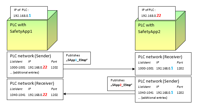
Type in the IP addresses of the respective remote terminal according to this figure. You have to modify the IP addresses of your network accordingly.
The destination network address
192.168.0.22has to be given the safety network variable lists of SafetyApp1 and the IP address192.168.0.1for the safety network variable lists of SafetyApp2. The entry at the sender must be made for the entry where the list identifiers match those at the corresponding receiver. This is done so that the packages can be assigned correctly by the subordinate layer.Important
In order to detect for which of the sender entries an IP is entered, a list of connected receivers can be displayed at the sender by means of the Show receivers button in the Safety Configuration tab. The editor of the connected safety network variable list (receiver) can be opened quickly by double-clicking an entry in this list. In the editor, you can check which pair of list identifiers is used by the receiver.
The project is configured for the cross-communication example.
To test the project, download both applications to the safety controllers. You might also have to make sure that the respective SafetyAppX_Mapping is downloaded to the controller and started. Afterwards, start the applications and reset any
SF_EmergencyStopPOUs by means of theResetinput and thebVar_Resetconnected variables in step 3.Now you can trigger the POU
SF_EmergencyStopin both interconnected controllers by triggering the emergency stop signal in one controller. In the example, the emergency stop switch is simulated by setting the global variable Local_EStop toFALSEon one of the two controllers and then writing the value for this controller by means of the command .
Example 2: Extension of the previous project with another device by "creating" the network variable components
Requirement: The project from example 1 has been created and it is open.
Add an additional standard controller to the project with a safety controller below it (context menu: Add Device).
Copy the POU and GVL objects from SafetyApp1 below the new safety controller.
Rename the new SafetyApp to SafetyApp3.
Add one Safety network variable list (Sender) and two Safety network variable list (Receiver) objects below SafetyApp3 by means of the Add Object command.
Open the Safety Configuration tabs of both safety network variable list (receiver) and select from the Associated Sender drop-down list the sender of SafetyApp1 for the first safety network variable list (receiver) and the sender of SafetyApp2 and for the second one.
If necessary, modify the Watchdog time in the safety network variable list (receiver).
Tip
The connection ID is preset with a project-wide unique value when the object is inserted. Therefore it no longer needs to be modified during the procedure described in this example.
Declare the variable
SApp3_EStopof data typeSAFEBOOLin the new Safety network variable list (Sender).Tip
The safety address of the variable list is preset with a project-wide unique value when the object is inserted. Therefore it no longer needs to be modified during this procedure. The group of variable list identifiers is also preset with a project-wide unique value in order to avoid conflicts.
Modify the assignment in the POU of SafetyApp3 so that the variable
Local_EStopis assigned to the variableSApp3_EStop. In this way, the value of the emergency stop switch is published by means of the Safety network variable list (Sender).Select the
ANDoperator, click Append Input in the context menu, and link this new input to the variableSApp1_EStop.The inputs of the
ANDoperator are now linked to theLocal_EStop,SApp2_EStop, andSApp1_EStopinputs.Set SafetyApp3 as the active application and build the application by clicking .
During the build operation, the system checks whether the project-wide safety network variable configuration matches and the SafetyApp3_Mapping is generated.
In the following steps, you will modify SafetyApp2.
Add a new Safety network variable list (Receiver) to SafetyApp2 and select the sender network variable list of SafetyApp3 from the Associated Sender drop-down list.
If necessary, modify the Watchdog time.
Open the POU of SafetyApp2 and add a new input to the
ANDoperator (context menu: Append Input). Link this new input to theSApp3_EStopvariable.In the following steps, you will modify SafetyApp1.
Add a new Safety network variable list (Receiver) to SafetyApp1 and select the sender network variable list of SafetyApp3 from the Associated Sender drop-down list.
If necessary, modify the Watchdog time.
Open the POU of SafetyApp1 and add a new input to the
ANDoperator (context menu: Append Input). Link this new input to theSApp3_EStopvariable.As in the previous example, the network configuration is described with explicit addresses.
Set the communication settings for all three controllers in the project so that it is possible to log in to the controllers later.
Deactivate the option Use default values for destination network address and port (255.255.255.255, 1202) in all safety network variable lists.
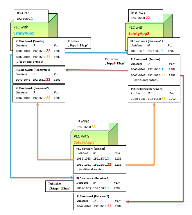
Type in the IP addresses of the respective remote terminals according to this figure. You have to modify the IP addresses of your network accordingly.
For Safety App3 this operation is described in more detail in the following steps:
Type in the Destination network address
192.168.0.22of the controller with SafetyApp2 as the entry for the List identifiers1080 1081in the PLC Network tab of the safety network variable list (sender) of SafetyApp3.Important
Make sure that you assign the destination network addresses to the correct list identifiers, otherwise the transfer of network variables will not work.
Open the safety network variable list (receiver) that imports the variable
SApp2_EStop. Type in the Destination network address of the controller with SafetyApp2192.168.0.22.Then type in the Destination network address
192.168.0.1for the controller with SafetyApp1 at the following locations:First in the safety network variable list (sender) for the list identifiers
1082 1083and then in the safety network variable list (receiver) that imports the variableSApp1_EStop.Now the project is configured for cross-communication.
To test the cross-communication example, first download the applications to all controllers involved and start the applications. Make sure that the respective SafetyAppX_Mapping is also running.
The
SAppX_EStopvariables published using the safety network variables are now transferred to the POUs of the other SafetyApps with the valueTRUE. This is the initial value that is written to theSAppX_EStopvariables by the simulated emergency stop switches.If necessary, set the
SF_EmergencyStopPOUs by means of theResetinput and the connectedbVar_Resetvariables.Now you can trigger the POU
SF_EmergencyStopin all three interconnected controllers by triggering the emergency stop signal in one controller. In the example, the emergency stop switch is simulated by setting the global variableLocal_EStoptoFALSEon one of the controllers and then writing the value for this controller by means of the command .