Programming in the Ladder Editor
Requirement: In your project, you have created a POU in the Ladder (CODESYS Ladder) implementation language. You have this POU open and ready to be edited in the ladder editor.
The following instructions describe only individual actions when working in the editor. No specific program is created.
If necessary, see also: Navigation in the Ladder Editor
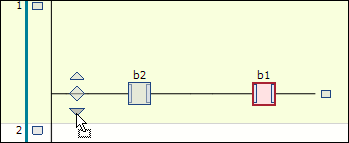
Insert: In the toolbox (ToolBox view) of the editor, select the Contact element, for example, and drag it to the network. Press and hold the mouse button. When you drag across the network, possible insertion positions are indicated by the following icons:
Square with a gray background inside an existing element symbol
Rhombus on a connecting line
Triangle pointing up or down for insertion above or below
You can insert the contact element when the mouse pointer gets a plus symbol (
 ). Release the mouse button at such a position.
The contact is inserted in the processing line of the network.
Insert Block: Insert a Block element in the network. Replace the three question marks
???in the element box with the name of the desired block from the project or a library. To do this, double-click the question marks and ideally use the Input Assistant by clicking the button.
Update Block: If you call a function block, for example, from your project in the ladder, then you also need to update in the ladder diagram after making a change to the base FB. To do this, execute the Update Parameters command.
Insert Input: Insert an Input element before the block. To assign variables, replace the three question marks
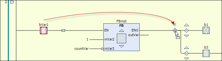
???at the element with the variable name. If necessary, the standard Auto Declare dialog opens.Select, Reposition: Reposition elements in the network: Select an element so that it is highlighted in red. In the case of a block, the box inside the block symbol has to be displayed with a red background. Drag the element to another possible insertion position until the cursor symbol becomes a square and release the mouse button.
Replace: To replace an existing element with another one, drag the new element onto the one you want to replace. When the element to be replaced itself lights up green as an insertion point, release the mouse button.
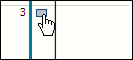
Add new network: Drag the Network element to the implementation part.
You will see rectangular insertion points in the left margin where the network numbering is displayed. The new network is inserted above the insertion point.
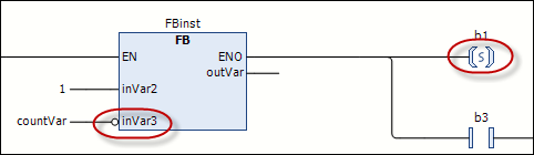
Provide the elements in the network with modifiers. For example, select the input pin of a block and open the context menu. For example, click the Negate command to negate an input, or one of the Set/Reset or edge detection commands (Edge Detection – Rising Edge, Edge Detection – Falling Edge).
The input is marked with the corresponding symbol.
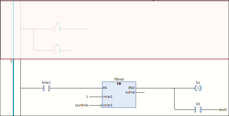
Example: Negated input at the block, set coil
Important
To switch the processing order in networks V1.2.0.0 and higher, see: Processing order and "normalization"
Unlike the LDFBD editor, there are no elements for Branches in the ladder editor of CODESYS Ladder. You create and edit branches exclusively by positioning or repositioning elements. Examples:
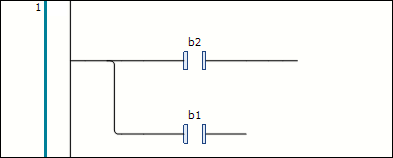
Create the following network:
Drag the second contact to the insertion position marked with a downward pointing arrow in front of the first contact.
A parallel branch open to the end is created. Each branch contains a contact.
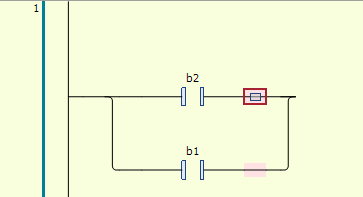
To create a closed branch from the open branch (to program an
ORconstruct), proceed as follows: In both branches, select after the contact element (multiselection). The selection is indicated by the small square with a red background on the line. Then click Close Parallel Branch.The two parallel branches open at the end become a closed branch.
There are two ways to reopen the closed branch:
You select one of the two branches and drag the selection box to that of the other branch.
You select both branches and click Open Parallel Branch. Note: If you have closed branches of multiple parallel branches, then the Open Parallel Branch command will always open all branches.
Select a network so that it is completely displayed with a red background. In the context menu, click Outcommented.
The network contents are displayed in gray and the texts in italics. The network is not included during processing.
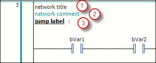
You can add a network title (1), a network comment (2), and/or a jump label (3) to a network. To do this, click in the first, second, or third line in the upper left corner of the network. A jump label is used as a target when inserting a Jump element.
The display of the network title and network comment is defined in the Ladder editor (LD2) category of the CODESYS options.