Overview
The basic unit of the FBD and LD programming is a network. Every network contains a structure which can represent 1) a logical or arithmetic expression, 2) the call of a POU (function, function block, program, or library POU), or 3) a jump or a return instruction.
IL actually requires no networks. However, in CODESYS an IL program also consists of at least one network in order to support conversion to FBD or LD. In view of this, you should also divide an IL program meaningfully into networks.
Function Block Diagram (FBD)
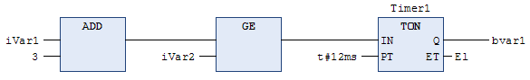
The function block diagram is a graphically oriented IEC 61131 programming language. It works with a list of networks. In this way, each network contains a structure which can contain logical and arithmetic expressions, calls of function blocks, a jump, or a return statement.
Boxes, which are familiar from Boolean algebra, are used here. Boxes and variables are connected by connecting lines. The signal flow in the network runs from left to right. The signal flow in the editor runs from top to bottom, starting with network 1.
Tip
CFC is also a programming language based on the same principle as FBD, but with the following differences:
The CFC editor is not network-oriented.
You can freely place the elements in the CFC editor.
Direct insertion of feedback paths is possible.
The order of execution is determined by a list of currently inserted elements, which you can change.
For more information, see the following: Programming in the Function Block Diagram (FBD)
Ladder Diagram (LD)
The ladder diagram (LD) is a graphically oriented programming language which is similar to an electrical circuit diagram.
On the one hand, the ladder diagram is suitable for designing logical switching units, but on the other you can also create networks just as in FBD. Because of this, you can use LD very well for controlling calls of other program blocks.
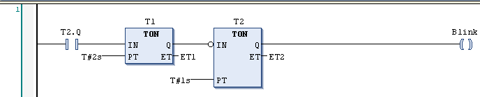
The ladder diagram consists of a series of networks. A network is bounded on the left side by a vertical line (bus bar). A network contains a circuit diagram of contacts, coils, optional boxes (POUs), and connecting lines.
On the left side of a network, there is a contact or a series of contacts which relay the ON or OFF state, which corresponds to the Boolean values TRUE and FALSE, from left to right. A Boolean variable is associated with each contact. When this variable is TRUE, the status is relayed from left to right via the connection line. Otherwise OFF is relayed. As a result, the coil(s) in the right part of the network receive(s) the value ON or OFF coming from the left and the value TRUE or FALSE is written accordingly into the Boolean variable assigned to them.
When the elements are connected in series, this means an AND operation. When they are connected in parallel, this means an OR operation. A line through an element means a negation of the element.
The negation of an input or an output is indicated by a circle symbol.
IEC 61131-3 defines a complete LD command set, consisting of different types of contacts and coils. Contacts conduct the current (according to their type) from left to right. Coils store the incoming value. Contacts and coils are assigned to Boolean variables. You can supplement an LD network with jumps, returns, labels, and comments.
Instruction List (IL)
The instruction list is an assembler-like IEC 61131-compliant programming language.
It supports accumulator-based programming.
An instruction list (IL) consists of a series of instructions. Each instruction starts on a new line and contains an operator and one or more operands separated by commas, depending on the type of operation.
A label followed by a colon can be placed in front of an instruction. It is used for the identification of the instruction and you can use the label as a jump destination.
A comment must be the last element in a line. Empty lines can be inserted between instructions.
All IEC 61131-3 operators are supported, as are multiple inputs, multiple outputs, negations, comments, set/reset of outputs, and conditional/unconditional jumps.
Each instruction is based primarily on the loading of values into the accumulator (LD instruction). After that, the corresponding operation is executed with the parameter from the accumulator. The result of the operation is written again into the accumulator, from where you should specifically store it with the help of an ST instruction.
The instruction list supports comparison operators (EQ, GT, LT, GE, LE, NE) and jumps for programming of conditional executions or loops. Jumps can be unconditional (JMP) or conditional (JMPC / JMPCN). In the case of conditional jumps, a check is performed as to whether the value in the accumulator is TRUE or FALSE.
