Example: Programming with the Ladder Diagram Editor
Product: CODESYS Visualization
This example shows how to implement a visualization where a ladder diagram editor allows for immediate programming of a PLC.
The sample package contains the VisuLadder library and the VisuLadderExample sample project.
The VisuLadder library provides the ladder diagram editor and a function block for accessing 8 I/Os. The editor can be instantiated in a PLC program.
The VisuLadderExample project shows how to use the VisuLadder library.
Description
In the VisuLadder library, a simple ladder logic is implemented for a PLC with 8 inputs and 8 outputs.
Using the CallLadder function block, you get access to 8 I/Os. The function block has 8 inputs and 8 outputs and can be programmed by the visualization user in the ladder diagram editor. You can instantiate CallLadder in different projects.
The VisuLadderMain editor visualization runs on the standard visualization of the controller. When the visualization is running in test mode, users can test their own created programs online.
Additional information
The library contains the CallLaddder function block and the corresponding VisuLadderMain visualization, as well as others. Each of the function blocks can be instantiated multiple times.
The VisuLadderExample project shows how to use the CallLadder function block with two instances.
Functional scope:
8 inputs
8 outputs
4 markers
Integrated functions:
Contact,Negate,TON,F_TRIG,R_TRIG,OR,AND8 networks per instance, 4 contacts per network, 1 output
Test mode
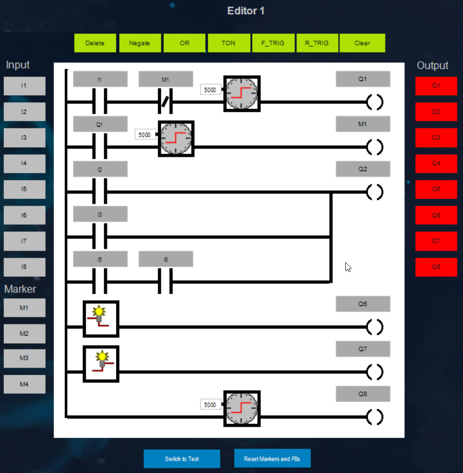
Programming
You can place an element in the editor by selecting a function and then the target position. It is also possible to select the target position first and then the function. A second click on the selected element deletes the selection.
 |
| Sets the input |
| Sets the marker |
| Sets the output |
| Deletes the selected element |
| Negates the selected contact |
| Creates or deletes an OR link with the previous network output |
| Sets the timer function block |
| Sets the |
| Sets the |
| |
| Sets all markers to |
| Activates the test mode This function is available in test mode and programming mode. |
Note
Markers and function blocks are used both in programming mode and in test mode. The "Reset Markers and FBs" function affects both operating modes.
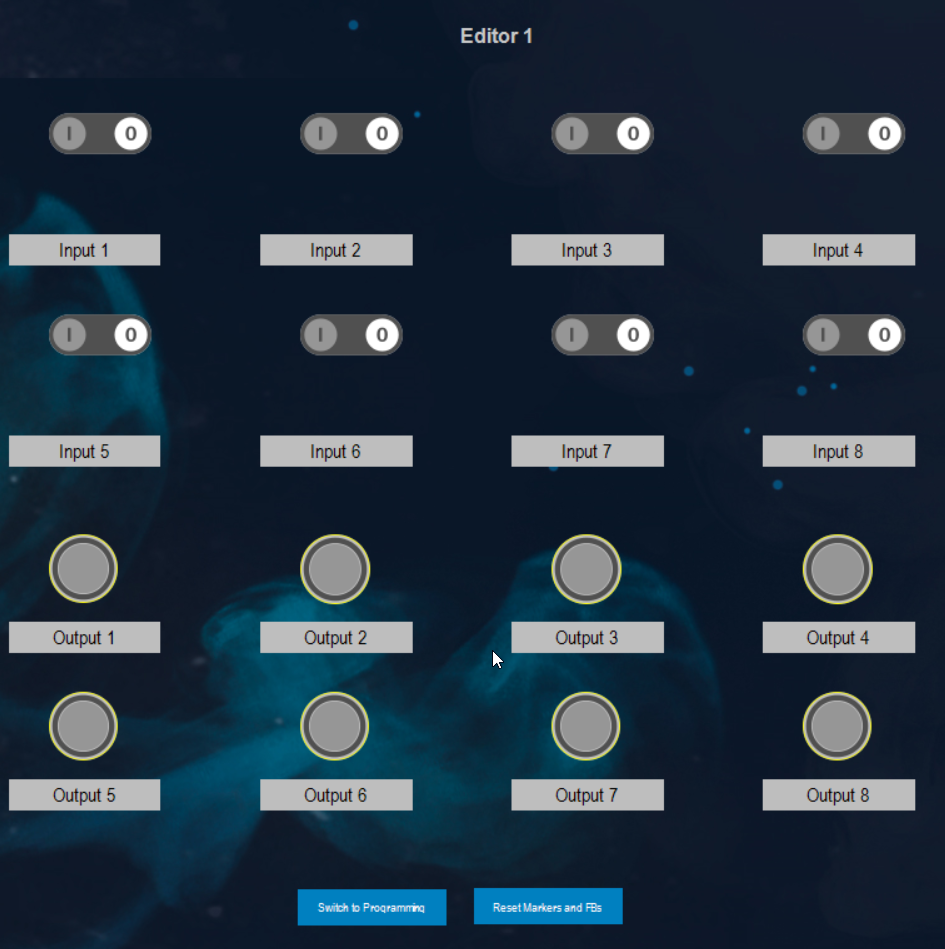
Test mode
The test mode can be activated by clicking the "Switch to Test"" button. All inputs and outputs are then decoupled. The values are retained.
In test mode, the program can be tested online with 8 keys for inputs and 8 lamps for outputs.
 |
System requirements and restrictions
Programming system | CODESYS Development System (version 3.5.16.1 or higher) |
Runtime system | CODESYS Control Win (version 3.5.16.1 or higher) |
Add-on components | - |
Note
 DOWNLOAD Project