Example: HMI
Product: CODESYS Visualization
The example package HMI Example contains examples for connecting CODESYS HMI to a CODESYS V3 and V2.3 control.
Description
 |
The example project HMIDemo.project shows the following features:
Use of function blocks and projects from libraries
Linking of data sources
Use of alarms
Use of trend elements
Use of recipe elements
Additional information
To successfully run the HMIDemo.project sample project, you also need the following library and projects:
LibForHMIDemo.libraryThe
LibForHMIDemolibrary is used to show how to use visualizations with a parameter interface from a library and link them to a data source.V3ProjForHMIDemo.projectSample project for V3 controllers. It provides data for the
HMIDemoin a V3 controller.V23Proj.proSample project for V2.3 controllers. It provides data for the
HMIDemoof a V2.3 controller.
Connecting a CODESYS V3 controller:
Install CODESYS V3.5 SP11 Patch 1 or higher and download the
V3ProjForHMIDemo.projectproject to the CODESYS Control Win controller.On the Communication Settings tab of the data source, adjust the "Name" and "Address" communication settings of the controller accordingly. To do this, in the device tree under the Data Sources Manager object, double-click the DatasourceV3 object and select the Communication Settings tab.
For more information, see: Device Editor – Editing the Communication
Connecting a CoDeSys V2.3 controller
Install CoDeSys V2.3 and load the
V23Proj.proproject on aPLCWinNT.On the Communication Settings tab of the data source, adjust the IP address communication setting of the controller accordingly. To do this, in the device tree under the Data Sources Manager object, double-click the Datasource object and select the Communication Settings tab.
For more information, see: Device Editor – Editing the Communication
Visualizations
VisualizationThe
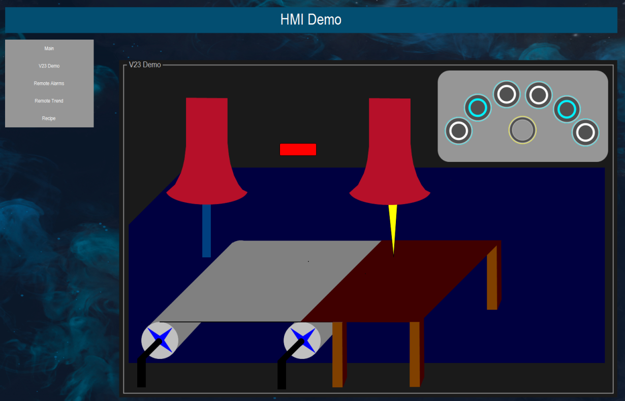
Visualizationvisualization shows how to use function blocks and visualizations from libraries in the HMI. (For more precise information about this, in the device tree under the Data Source Manager object, double-click the DatasourceV3 object and select the Type Mappings tab.) The switch can be used to start and stop the simulation of a sawtooth signal. The current value of the signal is displayed below.V23DemoConnection to a CoDeSys V2.3 controller
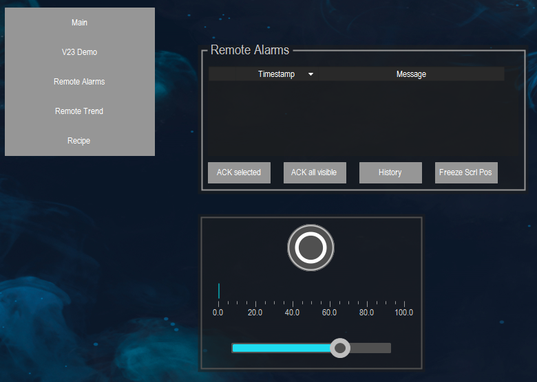
AlarmsThis visualization shows how to display and acknowledge alarms of a V3 controller connected via a data source. An alarm is triggered when the slider exceeds 60% of the maximum value.
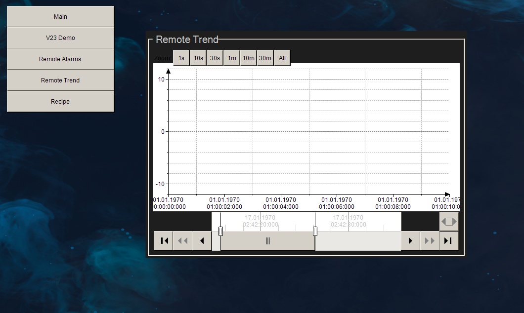
TrendIn this visualization, the trend element is used to display a CODESYS V3 trend recording of a controller connected via a data source. For this, the simulation of the sawtooth signal has to be activated.
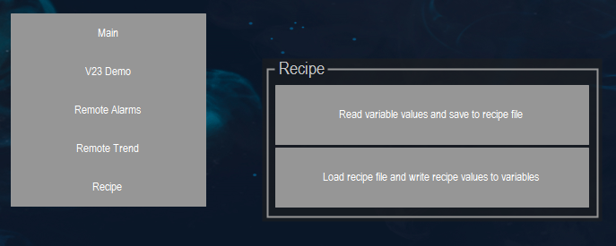
RecipeThis visualization shows how to use the HMI to load and save recipes. The recipes read and write values of the connected controllers.
System requirements and restrictions
Programming system | CODESYS Development System (version 3.5.14.0 or higher) |
Runtime system | CODESYS Control Win (version 3.5.14.0) |
Add-on components | - |
Note
 DOWNLOAD Project