Example: Using the ControlLoopLibrary Library
Product: Using the ControlLoopLibrary Library
The examples show how to use the function blocks from the ControlLoopLibrary library to implement components of digital control engineering.
Description
The ControlElement Libraries Examples package includes four projects:
FilterSampleTransferFunctionsSampleWaterLevelSampleWaterLevelSampleExtended
Project: FilterSample
The FilterSample sample project shows how to filter a noisy signal by using the following filters from control engineering:
FIR (Finite Impulse Response)
IIR (Infinite Impulse Response)
SOS (Second-Order Sections)
The sample implementations are available in ST and CFC.
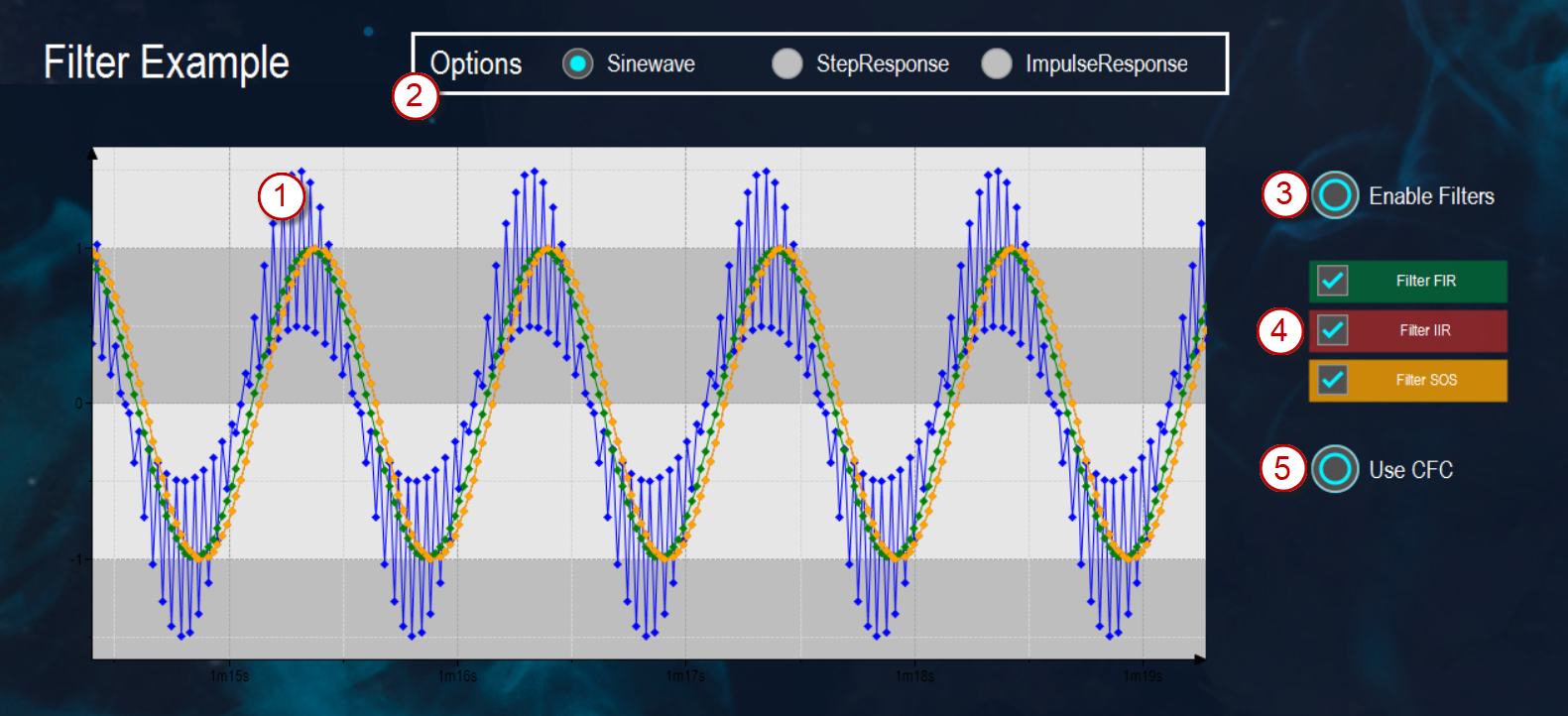
(1) |
| Blue signal waveform: The program simulates a noisy signal to be filtered. | |
(2) | Options | Sinewave | The noisy signal is configured as a sine wave using the |
StepResponse | The noisy signal is configured in steps using the | ||
ImpulseResponse | The noisy signal is configured as an impulse using the | ||
(3) | Enable Filters | Turns the applicable filters on and off. The filtering can be set independently of the current selection. | |
(4) | Filter FIR | Green signal curve: The signal is filtered through the FIR filter. | |
Filter IIR | Red signal curve: The signal is filtered through the IIR filter. | ||
Filter SOS | Yellow signal curve: The signal is filtered through the SOS filter. | ||
(5) | Use CFC | Select whether the program runs in the background as ST or as CFC. | |
Project: TransferFunctionsSample
The TransferFunctionsSample project includes the following applications:
Application_ControlLoopApplication_StepResponse
Application: Application_ControlLoop
The Application_ControlLoop application represents a model of a control loop. A PI controller serves as the control unit.
In the example, a PT1 transfer function represents a motor as the actuator of the controlled system.
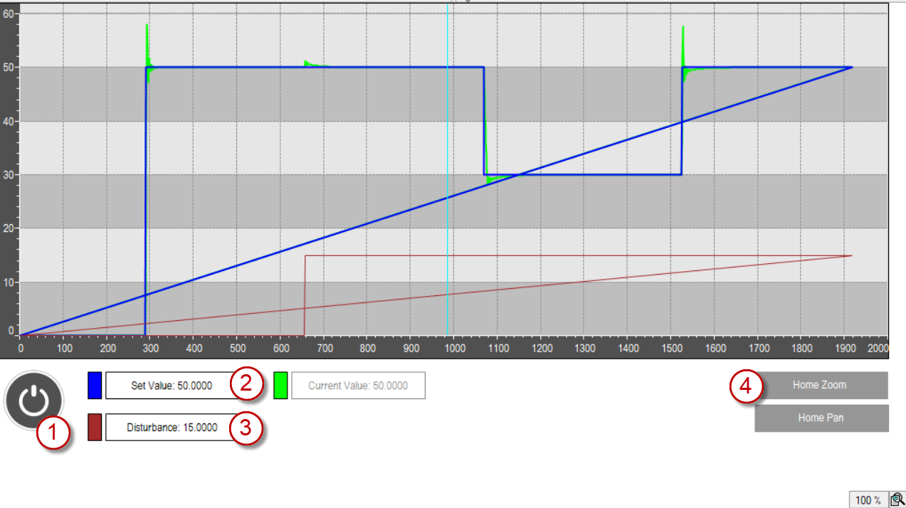
(1) |
| Starts the simulation; another click resets the simulation. |
(2) | Set Value | Specifies the target value |
(3) | Disturbance | Specifies the magnitude of the disturbance. The |
(4) | Home Zoom | Resets the view to see the entire data curve in the chart. |

Application: Application_StepResponse
The Application_StepResponse application shows the behavior of different transfer functions for specific parameters.
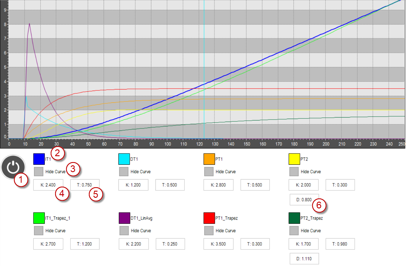
(1) |
| Starts the simulation; another click resets the simulation. |
(2) |  | The respective color of the data curve of a transfer function in the diagram. |
(3) | Hide Curve | Hides or shows the respective transfer function. |
(4) | K | Gain of the step response |
(5) | T | Time constant of the step response |
(6) | D | Damping of the step response |
Project: WaterLevelSample
The WaterLevelSample example shows a water tank whose fill level should be kept constant by various control strategies. Water flows continuously out through a valve at the bottom of the tank. The regulator controls the water flow into the tank in order to counteract the outflow.
Specifically, a PID control and various versions of a two-point controllers are used.
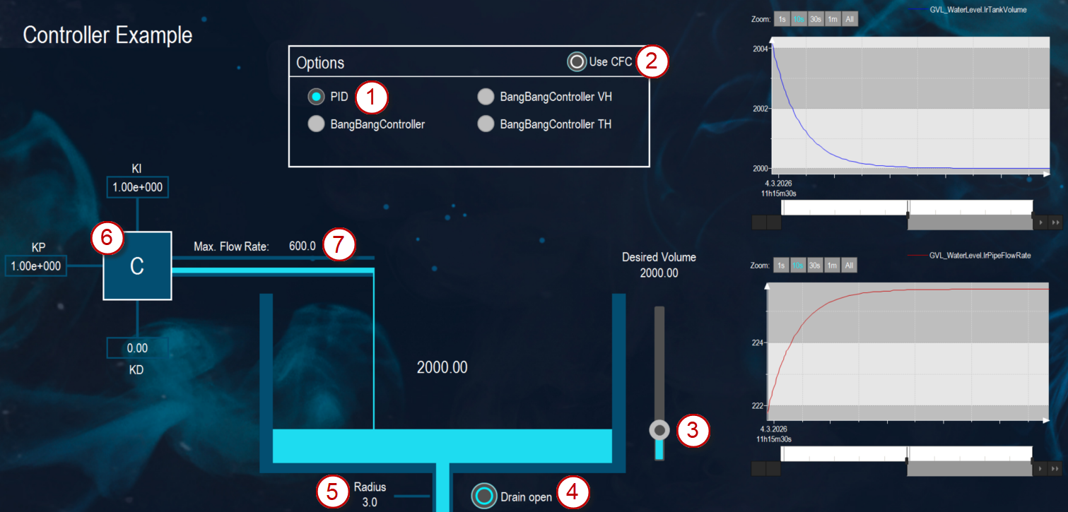
(1) | Options | PID | A PID control is used to regulate the set value. |
BangBangController BangBangController VH BangBangController TH | A bang-bang control is used to regulate the set value. | ||
(2) | Use CFC | Select whether the program runs in the background as ST or as CFC. | |
(3) | Desired Volume | The slider next to the water tank configures the desired target fill level. | |
(4) | Drain open | Opens and closes the drain valve | |
(5) | Radius | Changes the radius of the drain pipe | |
(6) | KI KP KD | Set the parameters for the PID control. | |
(7) | Max. Flow Rate | Sets the maximum flow rate of the water inlet pipe. | |
Project: WaterLevelSampleExtended
The WaterLevelSampleExtended project is based on the WaterLevelSample example.
It also shows how to use a three-point controller.
System requirements and restrictions
Programming system | CODESYS Development System Version 3.5.18.50 or higher |
Runtime system | CODESYS Control Win Version 3.5.18.50 or higher Note: Use the free Device Reader application (available in the CODESYS Store International) to find out the functions supported by the controller. |
Add-on components | - |
Additional requirements | - |