Example: IO Mapping Tool
Product: CODESYS Development System
You can use the IEC library IO Mapping Tool to remap the inputs and outputs of a program to each other via a visualization in runtime mode.
 |
Description
The inputs and outputs are mapped via function blocks and the corresponding visualizations. In doing so, the function blocks are simply activated between the desired inputs our outputs.
Function blocks with eight inputs and outputs:
Basic function block
Function block for BOOL inputs and outputs
Function block for BYTE inputs and outputs
Function block for WORD inputs and outputs
Function blocks with a variable number of inputs and outputs
Basic function block
Function block for BOOL inputs and outputs
Function block for BYTE inputs and outputs
Function block for WORD inputs and outputs
Function blocks with eight inputs and outputs
In the IOMappingBool, IOMappingByte, and IOMappingWord function blocks, eight variables each of the corresponding type are used for the inputs and outputs.
Function blocks with variable inputs and outputs
In the VarIOMappingBool, VarIOMappingByte, and VarIOMappingWord function blocks, the inputs and outputs are mapped via arrays of length g_iMaxIOs. The g_iMaxIOs parameter can be set via the Param parameter list and it can be maximum 256.
Basic function blocks
In the IOMappingBaseFB and VarIOMappingBaseFB function blocks, an array of integer values is created for each. The indices of the array represent the inputs and the values at the corresponding positions represent the outputs for these inputs. Only one input can point to one output at a time. When changing the mapping of inputs and outputs, it is checked whether or not the output has already been mapped to an input. If this is the case, then the value of the earlier input is set to -1. The array that saves the mapping of inputs to outputs is stored with the PersistenceManager.
Additional information
Visualization
Two visualizations are included in the library. One visualization shows a fixed number of inputs and outputs and the other visualization shows a variable number of inputs and outputs.
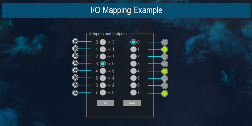
The eight inputs and outputs in the IOMappingVisu visualization are each represented by eight radio buttons. When a radio button is selected on the left side, the corresponding output is automatically selected on the right side. By default, the outputs are ordered according to the inputs. After changing the mapping, the new mapping is saved by clicking the "Set" button. Clicking the "Reset" button discards all changes made after the last save.
In the VarIOMappingVisu visualization, the mapping is displayed and editable by means of combo boxes. The left field represents the inputs and the right field represents the outputs. The current mapping is displayed clearly in the adjacent table.
The "Set" and "Reset" buttons work in the same way as for IOMappingVisu.
Sample project
The IOMappingExample sample project shows how to use the IOMappingBoolFB, and VarIOMappingBoolFB function blocks. The mapping of values is saved by means of the PersistenceManager. For this purpose, the AC_Persistence library has to be linked in the POU pool and added as a module instance (see also: "Persistence Manager" in the CODESYS Help).
System requirements and restrictions
Programming system | CODESYS Development System (version 3.5.17.0 or higher) |
Runtime system | CODESYS Control Win (version 3.5.17.0) |
Add-on components | - |
Note
 DOWNLOAD Project