Example: Mapping
Product: CODESYS Application Composer
This example shows the default options for I/O mapping of the modules using the mapping editor. The hardware available in the CODESYS Application Composer project is used for this purpose.
Description
This example shows how to use the mapping editor to link the inputs and outputs of the module instances.
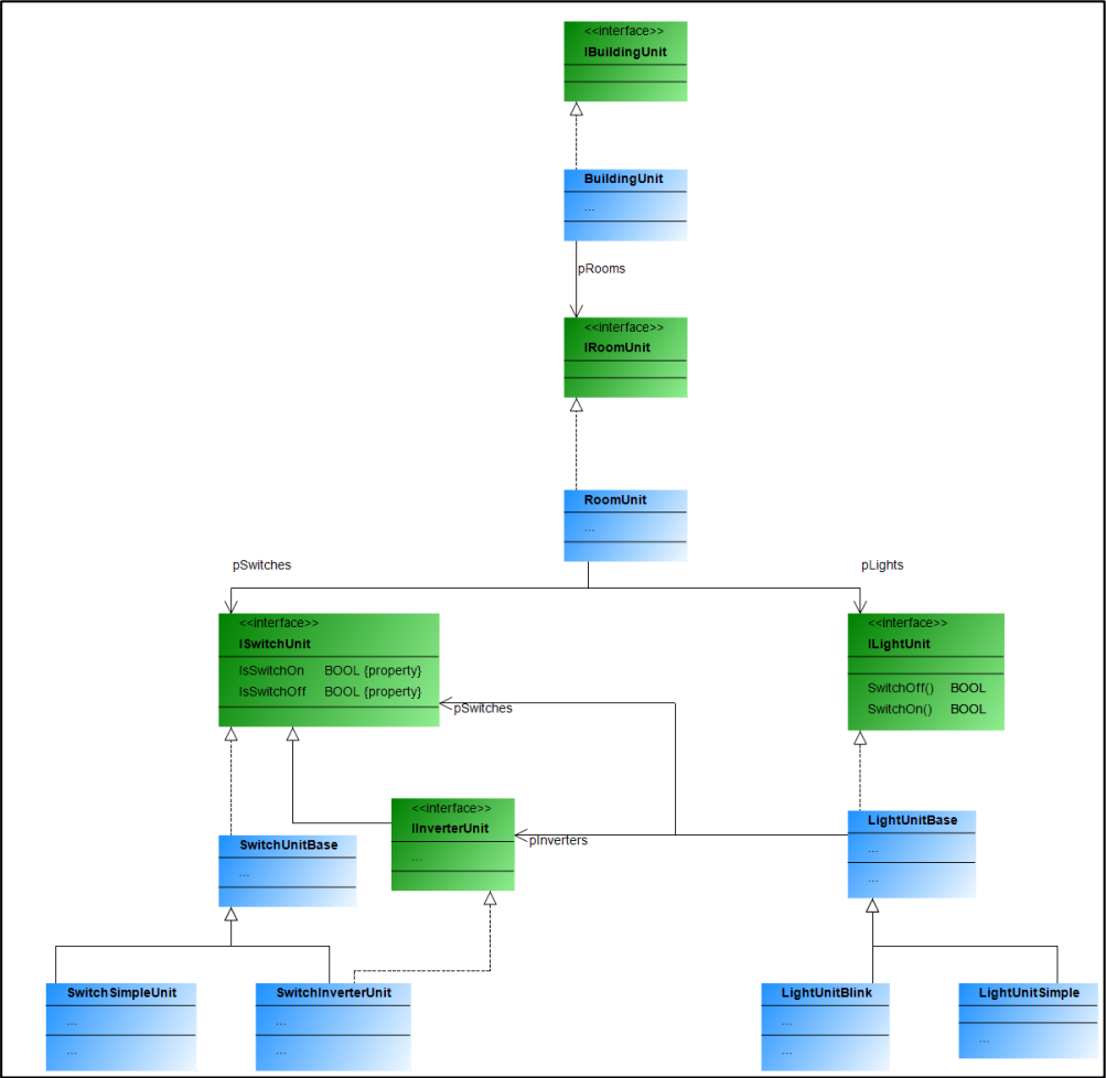
The example describes a building which contains rooms. These rooms have switches and lights, each of which is available in two variants. The lights (blinking or steady) can be linked to switches or -buttons. A switch or-button can be linked to several lights. For example, if a light is equipped with both a switch and buttons, then the switch behaves as a main switch which must be pressed before the lights can be operated with the push-buttons. If only switches are installed, then these switch the referencing light. A blinking light automatically switches between on and off when it is switched on.
Module declarations
Function block declarations
Device tree
Module tree
 |
For more information, see: Command: Map I/Os.
Additional information
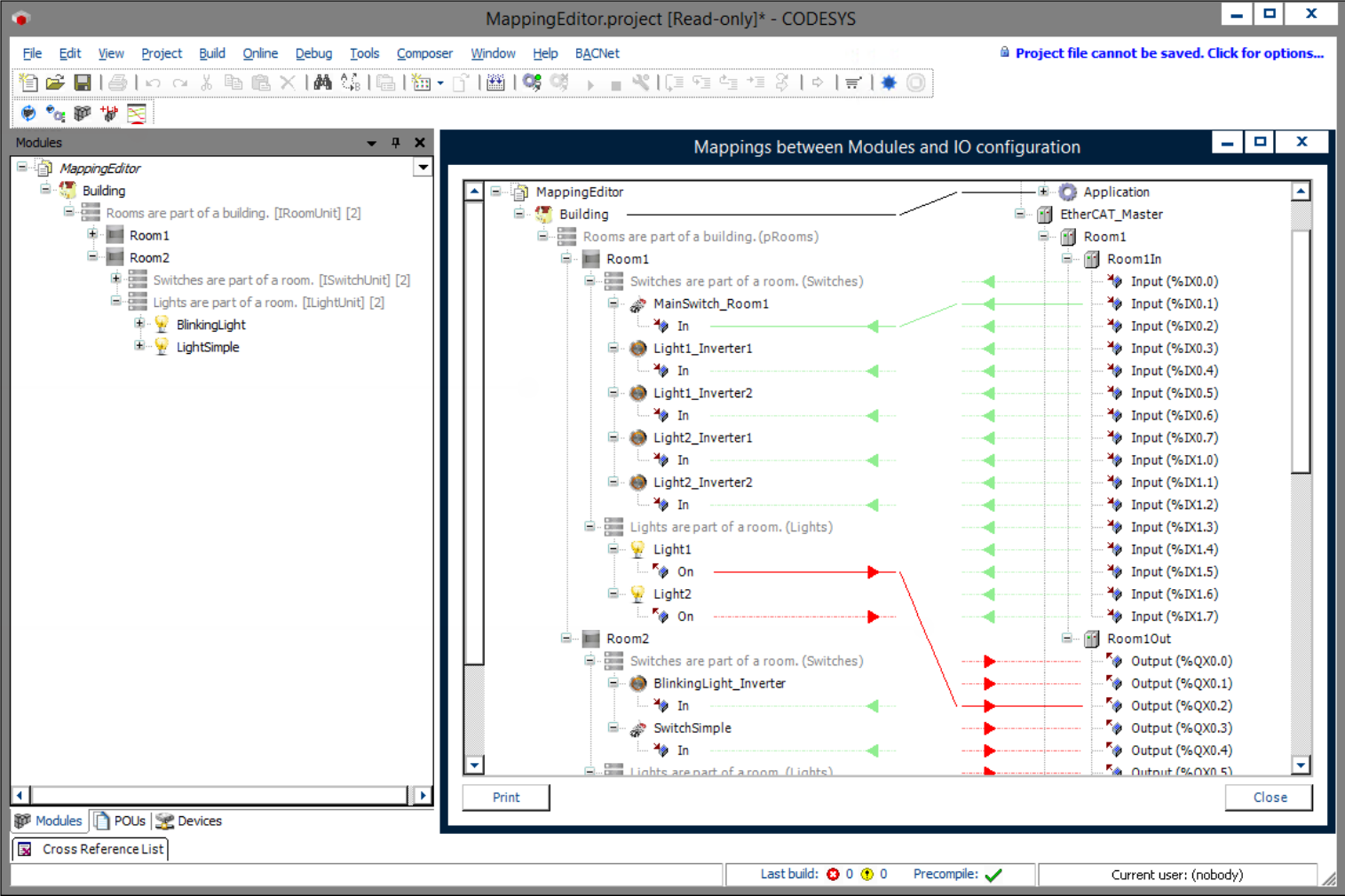
The devices of the bus system are available even before generation, but without a link to the inputs and outputs of the modules. You use the mapping editor to link these I/Os to those of the communication system. The mapping editor can be accessed by clicking the following icon in the Composer menu:
In the mapping editor, you can drag and drop to link the inputs and outputs of the two pages. The mapping editor can also be used when the devices have been generated automatically during code generation by means of the device generator. It is also possible to use this to link inputs and outputs of module instances which are not mapped to fieldbus I/Os.
 |
System requirements and restrictions
Programming system | CODESYS Development System (version 3.5.17.0 or higher) |
Runtime system | CODESYS Control Win (version 3.5.17.0) |
Add-on components | CODESYS Application Composer |
Note
 DOWNLOAD Projects