Tab: EtherCAT Master – General
The tab is used for the configuration of the basic settings for the EtherCAT Master. The basic settings are preset from the device description file.
Settings of the configuration parameters
Important
The auto-configuration mode (Autoconfig master/slaves option) is selected by default and is adequate for standard applications. If the mode is not selected, then all configuration settings for the master and the slave(s) have to be done manually. Expert knowledge is required to do this. The auto-configuration mode option has to be switched off to configure slave-to-slave communication.
Autoconfig master/slaves |
Even if this option of the master is selected, an expert mode can be enabled explicitly for each individual slave, which allows for manual editing of the automatically generated process data configuration. |

Target address (MAC) | MAC address of the device in the EtherCAT network that is to receive the telegrams. . Options
|
Source address (MAC) | MAC address of the controller (target system) or network name (name of the adapter or PLC (target system)) |
Network name | Name or MAC of the network, depending on which of the following options is selected: |
Select network by MAC |
|
Select network by name |
|
Scan | Scans the network for the MAC IDs or names of the target devices that are currently available. |
These settings are displayed only when the Redundancy option is selected. Here the parameters of the additional device are defined according to the description for EtherCAT NIC Settings. |
Cycle time (µs) | Time span after which a new data telegram is dispatched on the bus. When the Distributed Clock function is enabled in the slave, the master cycle time specified here is transferred to the slave clocks. As a result, a precise synchronization of the data exchange can be achieved. This is particularly important when spatially distributed processes require simultaneous actions. An example of a simultaneous action is applications in which multiple axes have to execute coordinated movements at the same time. A very precise, network-wide time base with a jitter of considerably less than 1 microsecond can be achieved in this way. |
Sync offset | Parameter for setting the delay time between the DC time base of the EtherCAT Slave and the cycle start of the PLC. The default value is 20%. This time is active at the same time for all slaves with DC. An offset of 20% means that the timer interrupt in the EtherCAT Slave takes place 20% before the next IEC cycle. This means in the case of
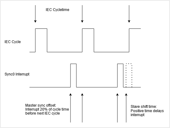 If DC is active at the corresponding slave, then the default settings come from the respective ESI file. The device manufacturer can define additional offsets here in the form of the Shift time for both Sync 0 and Sync 1 timer interrupts. When the expert setting is enabled at the slave, these times can be changed manually. The Shift time is entered into the register ImportantIt must be prevented at all costs that the sync interrupt takes place near the time of the IEC cycle because otherwise no data can exist for one cycle and devices go into synchronization error. Both offsets from the master and the individual offset of each slave have to be considered for this. With the normal setting of 20% offset for the master and 0% for the slaves, the jitter of the IEC cycle and the delays of the transmission timing by the system can be a maximum of +80% and –20%. |
Sync window monitoring |
|
Sync window | Time for Sync window monitoring. When the synchronization of all slaves is within this time window, the variable |
Use LRW instead of LWR/LRD |
|
Messages per task |
|
Automatically restart slaves |
|
This functionality enables communication from an external device configuration tool via the mailbox gateway to the EtherCAT devices. The wiring does not have to be changed. In general, all specified mailbox protocols (CoE, FoE, VoE, SoE) can be used. | |
Enable |
|
IP address | IP address for the UDP connection. The UDP port is set to 0x88a4. Options
|
These settings can be edited only when the Autoconfig master/slaves option is deactivated. Otherwise this is done automatically and they are not visible here. | |
Image In Address | First logical address of the first slave for input data |
Image Out Address | First logical address of the first slave for output data |