Programming the Controller Application in the Project
Declaring the global variables
First, declare the variables that you want to use across the entire application. To do this, create a global variable list below Application:
Select the
Applicationentry and click in the context menu. Change the default nameGVLtoGlob_Varand click Add to confirm.The

Glob_Varobject is displayed below
Application. The GVL editor opens to the right of the device tree.When the textual view opens, it already contains the keywords
VAR_GLOBALandEND_VAR. For our example, click the button on the right sidebar of the editor to activate the tabular view.
An empty row appears. The cursor is in the Name column.
In the context menu, click Insert.
An input field opens. At the same time, the Scope
VAR_GLOBALand the Data typeBOOLare entered in the line automatically.Specify
rTempActualin the Name field.Double-click in the field of the Data Type column.
Now the field can be edited and the
 button is displayed.
Click the
button and then select Input Assistant.The Input Assistant dialog opens.
Select the data type
REALand click OK.Enter a numerical value in the Initialization column (example:
8.0).
Declare the following variables in the same way:
Name | Data Type | Initialization | Comment |
|---|---|---|---|
|
|
| Actual temperature |
|
|
| Set temperature |
|
|
| Status of door |
|
|
| Time after compressor runs that a signal sounds |
|
|
| Time after opening the door that a signal sounds |
|
|
| Control signal |
|
|
| Control signal |
|
|
| Status message |
Creating the main program for the cooling control in the CFC editor
You will now describe the main function of the application program in the main PLC_PRG POU, which is created by default. The compressor is activated and cools when the actual temperature is higher than the set temperature plus a hysteresis. The compressor switches off when the actual temperature is less than the set temperature minus the hysteresis.
To describe this functionality in the CFC implementation language, follow the steps below:
In the device tree, double-click
PLC_PRG.The CFC editor opens in the
PLC_PRGtab. The declaration editor appears above the graphical editor area in textual or tabular form. The ToolBox view is on the right side.In the ToolBox view, select the Input element and drag it to the CFC editor below the
PLC_PRGtab.The nameless entry
???has been inserted.In the CFC editor, click
???at the input, and then click to open the Input Assistant. In the Variables category, select the
 rTempActualvariable below . This is how to reference the global variablerTempActualhere.The input name is
Glob_Var.rTempActual.As in Step 3, create another input with the name of the global variable
Glob_Var.rTempSet.Create another input, and then click
???and replace them with the namerHysteresis.Because this is not the name of a known variable, the Auto Declare dialog opens. The name is already used in the dialog.
In the Auto Declare dialog, specify the Type as
REALand Initialization as1. Click the OK button.The variable
rHysteresisappears in the declaration editor.In the ToolBox view, select Block element and drag it to the CFC editor below the PLC_PRG tab.
The POU opens in the CFC Editor.
Replace
???withADD.The POU adds all inputs that are connected to it.
Connect the
Glob_Var.rTempSetinput to theADDPOU. To do this, click the output pin of the input and drag it to the upper input pin of theADDPOU.In the same way, connect the input
rHysteresiswith the lower input of theADDPOU.The two inputs
rHysteresisandGlob_Var.rTempSetare now added byADD.To move an element in the editor, click an empty space in the element or click the frame, so that the element is selected (red border, red highlight). Drag the element to the desired position.
Create another POU to the right of the
ADDPOU. Its purpose is to compareGlob_Var.rTempActualwith the sum ofGlob_Var.rTempSetandrHysteresis. Assign theGTfunction (greater than) to the POU.The
GTPOU works as follows:IF (upper input > lower input) THEN output := TRUE;Connect the input
Glob_Var.rTempActualto the upper input of theGTPOU.Connect the output of the
ADDPOU to the lower input of theGTPOU.Now use the block element to create a function block to the right of the
GTPOU which starts and stops the compressor depending on the input conditions (Set – Reset). Specify the nameSRin the???field. Press the Enter key to close the open input field above the POU (SR_0).The Auto Declare dialog opens.
Declare the variable with the name
SR_0and the data typeSR. Click the OK button.The
SRPOU from theStandardlibrary is instantiated.SRis used for the definition ofTHENat the output of the GT POU. The inputsSET1andRESETappear.Connect the output pin on the right of the
GTPOU to theSET1input of theSR_0POU.SRcan set a Boolean variable fromFALSEtoTRUEand back again. When the condition at the inputSET1is satisfied, the Boolean variable is set toTRUE. The variable is reset again when the condition atRESETis satisfied. The Boolean (global) variable in our example isGlob_Var.xCompressor.Create an Output element and assign it to the global variable
Glob_Var.xCompressor. Drag a connecting line betweenGlob_Var.xCompressorand the output pinQ1ofSR.
Now specify the condition under which the compressor should switch off again (in this case, the RESET input of the SR POU gets a TRUE signal). To do this, formulate the opposite condition to that above. Use the SUB (subtraction) and LT (less than) POUs to do this.
The result is the following CFC chart:

Creating a POU for signal management in the ladder diagram editor
In another POU, you will now implement the signal management for the alarm buzzer and for switching the lamp on and off. The ladder diagram (LD) implementation language is suitable for this.
Handle each of the following signals in their own networks:
When the compressor runs too long because the temperature is too high, a continuous audible signal sounds.
When the door is open too long, an intermittent signal sounds.
The light is on as long as the door is open.
In the device tree, right-click the
Applicationobject and add a POU object of type Program with the Ladder (LD2) implementation language.Name the program as
Signals.The
Signalsprogram is listed in the device tree next toPLC_PRG. The ladder diagram editor opens in theSignalstab. The declaration editor appears in the upper part, the ToolBox view to the right. The ladder diagram contains an empty network.Create a program in the network so that an audible signal sounds when the compressor runs too long without reaching the specified temperature. To do this, insert a
TONtimer POU in the next steps. It switches a Boolean signal toTRUEafter a specified time.In the ToolBox view, drag the Block element and drop it into the empty network to an available insertion position.
The block is displayed as a box with inputs and outputs.
Double-click the three question marks (
???) in the block and click the symbol in the line editor.
The Input Assistant dialog opens.
In the Input Assistant dialog, in the Standard function blocks category, in the Standard library, select the
TONTimer and click OK.Now in the line editor of the block, which shows the function block name
TON, press the Enter key.The
TONPOU is displayed with its inputs and outputs.To remove the
ENinput and theENOoutput, select the block and click the EN/ENO → EN in the context menu.Now the block has only the
INandPTinputs and theQandEToutputs.Double-click the three question marks [???] directly above the block, specify
TON_0as the instance name, and press the Enter key.You have confirmed the instance name. The Auto Declare dialog opens.
Click OK to confirm the dialog.
Now the inserted
TONPOU is instantiated with the nameTON_0.Program the block to be activated as soon as the compressor starts running. First drag the
Contactladder element from the ToolBox view in front of theINinput of the block. Double-click the three question marks and click the icon in the line editor (). In the Input Assistant, now select the already declared global variable xCompressor and click OK.The variable name
Glob_Var.xCompressoris displayed above the contact.Tip
When you begin to type a variable name at the input position, you automatically get a list of all variables with names that begin with the typed characters and can be used at this point. This assistance is a default setting in the CODESYS options for SmartCoding.
Insert the signal that is to be activated. To do this, drag a Coil from the ToolBox view, Ladder category, to the
Qoutput of theTONblock. Specify the nameGlob_Var.xSignalfor the coil.Define the time period from the activation of the POU
TON_0until the signal should sound. This definition takes place via the variableGlob_Var.timAlarmThreshold, which you insert for this purpose at the inputPTofTON_0. To do this, move the mouse pointer to the left end of the input pin of inputPT. Click the fine-edged box which is now displayed to left of the input pin and specify the variable name.Press the Enter key.
The Auto Declare dialog opens.
Click OK to confirm the dialog.
The newly declared variable is displayed in the declaration part.
Right-click the
TONPOU and click Remove unused pins in the context menu.The unused output
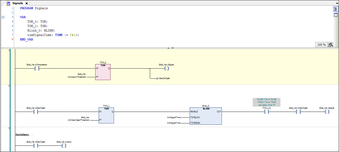
ETis removed.In the second network of the LD, program so that the signal sounds intermittently when the door is open too long.
Use the mouse to drag an Network element from the ToolBox view to the insertion point below Network 1.
An empty network with the number 2 appears.
As in the first network, implement a
TONPOU for time-controlled activation of the signal. This time it is triggered by the global variableGlob_Var.xDoorOpenat the inputIN. At the inputPT, add the global variableGlob_Var.timDoorOpenThreshold.From the
Utillibrary, add aBLINKPOU at the outputQof theTONPOU in this network and instantiate it with the nameBlink_0.The
BLINK_0POU clocks the signal forwardingQand thereforeGlob_Var.xSignal.First, drag two Contact elements from the ToolBox view to the
OUToutput of the POU. Assign the variableTON_1.Qto the contact directly after the outputQand the global variableGlob_Var.xDoorOpento the second contact.Insert a Coil element after the two contacts and assign the global variable
Glob_Var.xSignalto it.Declare the local variable
timSignalTime : TIME := T#1S;and insert this variable at the inputsTIMELOWandTIMEHIGH. The cycle time is 1 second forTRUEand 1 second forFALSE.Right-click the
TONPOU and click Remove unused pins in the context menu.The unused output
ETis removed.In the third network, program so that the lamp lights up as long as the door is open. Add an additional network and a contact. Assign the variable
GlobVar.xDoorOpento the contact.The inserted contact leads directly to a coil. Add a coil to the right of the contact and assign the global variable
Glob_Var.xLampto the coil.CODESYS processes the networks of an LD one after the other. Now install a jump to Network 3 at the end of Network 1 in order to ensure that either only Network 1 or only Network 2 is executed:
When you hover the mouse pointer over the 3rd line in the top left-hand edge of the network, the information <insert jump here> is displayed. Double-click this position and specify DoorIsOpen: as the jump label in the line editor.
Select the Network 1. From the ToolBox view, Ladder Diagram category, drag the Jump element to the insertion position marked with a triangle in front of the
Glob_Var.xSignalcoil.The jump element appears. The jump destination is still specified as
???.Double-click the three question marks [???] and click the
symbol in the line editor. In the Input Assistant dialog, select DoorIsOpenfrom the possible label identifiers and click OK to confirm.The label to Network 3 is implemented.
The LD program now looks like this:
Calling the "Signals" program in the main program
In our program sample, the main program PLC_PRG should call the Signals program for signal processing.
In the device tree, double-click
PLC_PRG.The
PLC_PRGprogram opens in the editor.In the Toolbox view, drag a Block element to the editor of
PLC_PRG.Double-click the three question marks [???] and click the
symbol in the line editor. In the Input Assistant dialog, in the POU / Program and Function Calls category, select the Signalsprogram and click OK to confirm.
Creating an ST POU for a simulation
Because the application in this example project is not linked to physical sensors and actuators, you also need to write a program for the simulation of increase and decrease in temperature. This will allow you to monitor the operation of the refrigerator controller afterwards in online mode.
You create the simulation program in structured text.
The program increases the temperature until the main program PLC_PRG determines that the set temperature has been exceeded. Then the program activates the compressor. Then the simulation program decreases the temperature until the main program deactivates the compressor again.
In the device tree, right-click the Application object and add a POU object of type Program with the Structured Text (ST) implementation language. Name the POU as
Simulation.Implement the following code in the ST editor:
Declaration part:
PROGRAM Simulation
VAR
        TON_1: TON;                         //The temperature is decreased on a time delay, when the comepressor has been activated
        P_Cooling: TIME:=T#500MS;
        xReduceTemp: BOOL;                  //Signal for dereasing the temperature
        TON_2: TON;                         //The temperature is increased on a time delay
        P_Environment: TIME:=T#2S;          //Delay time when the door is closed
        P_EnvironmentDoorOpen: TIME:=T#1S;  //Delay time when the door is open
        xRaiseTemp: BOOL;                   //Signal for increasing the temperature
        timTemp: TIME;                      //Delay time
        iCounter: INT;
END_VAR
Implementation part:
iCounter := iCounter + 1;     // No function, just for demonstration purposes.

// After the compressor has been activated due to TempActual being too high, the temperature decreases.
// The temperature is decremented by 0.1°C per cycle after a delay of P_Cooling
IF Glob_VAR.xCompressor THEN
        TON_1(IN:= Glob_Var.xCompressor, PT:= P_Cooling, Q=>xReduceTemp);
        IF xReduceTemp THEN
                Glob_Var.rTempActual := Glob_Var.rTempActual-0.1;
                TON_1(IN:=FALSE);
        END_IF
END_IF

//If the door is open, the warming occurs faster; SEL selects P_EnvironmentDoorOpen
timTemp:=SEL(Glob_Var.xDoorOpen, P_Environment, P_EnvironmentDoorOpen);

//If the compressor is not in operation, then the cooling chamber becomes warmer.
//The  temperature is incremented by 0.1°C per cycle after a delay of tTemp
TON_2(IN:= TRUE, PT:= timTemp, Q=>xRaiseTemp);
IF xRaiseTemp THEN
        Glob_Var.rTempActual := Glob_Var.rTempActual + 0.1;
        TON_2(IN:=FALSE);
END_IF
Tip
We recommend that you use a visualization for convenient operation and monitoring of the entire controller program. A visualization created with CODESYS Visualization is installed in the completed sample project for this tutorial, which is provided with the CODESYS standard installation (Projects directory). You can download this project to the controller and start it to see it working together with the visualization. When started, the Live_Visu begins with a representation of the refrigerator which reproduces the operation of the simulation program without you having to input any data. However, you can open and close the door by clicking the on/off switch. It is possible to adjust the default temperature by means of the needle of the rotary control. We will not cover the creation of the visualization in this tutorial. An corresponding tutorial is planned in the help for CODESYS Visualization.
Defining the programs to be executed in the task configuration
The default task configuration contains the call for the main program PLC_PRG. For our sample project, you also need to add the call for the Simulation program.
In the device tree, drag the
Simulationentry toMainTaskbelow the Task Configuration.The
Simulationprogram is inserted into the task configuration.To view the task configuration, double-click the
MainTaskentry to open the editor.In the table in the lower part of the editor, you see the POUs that are called by the task:
PLC_PRG(entered by default) andSimulation. The call type of the task is Cyclic at intervals of 20 milliseconds. In online mode, the task will execute the two POUs one time per cycle.
Defining the "active application" for the communication with the PLC
The name of the Application is displayed in bold in the Devices view. This means that this application is set as the "active application". The communication with the controller then refers to this application.
When there is only one application in a project, it automatically becomes the active application. If your application is not active yet, then activate it as follows:
In the context menu of
Application, click Set Active Application.Application is now displayed in bold in the Devices view.
Debugging the application program
When you are inputting the code, CODESYS immediately alerts you to syntax errors by means of a wavy red underline below the text in question. The result of the check is also shown in the message view. If necessary, click to open the message view. The messages are displayed in the Precompile message category. You can select a message and press the F4 key to jump to the corresponding point in the code. More tests of the application program are performed when the application is downloaded to the controller.
Afterwards, only an error-free application can be downloaded to the controller.