Device Tree and Device Editor
Device tree
In the Devices view (also called the "device tree"), you organize applications according to target device. In this view, you can see the PLC hardware and fieldbus systems, configure the hardware communication, and assign applications.
The root node of the device tree is a symbolic node entry: <project name>.
You insert device objects below this node for one or more PLCs, also referred to as "target systems". Each device object represents a specific hardware component, for example a controller, fieldbus, bus coupler, drive, I/O module, or monitor. When you add objects, an add assistant helps you by offering all possible devices from your local device repository.
If you are already connected to a controller network, then you can scan the hardware for available devices and save them to the device tree in the current configuration.
For creating device objects in the device tree (mapping to the controlling hardware environment), specific rules apply (see below). The hierarchical layout of application objects and device objects defined the scope of other objects, such as libraries and GVLs.
There are programmable devices and strictly parameterizable devices. The device type defines the possible insertion point in the device tree and the selection of objects that you can insert below the device. Programmable devices automatically get an additional PLC Logic node below the device object, which is strictly for organizational purposes. Below this node, you insert the objects that are required for programming the device (this means the application(s) and GVLs or text lists, for example).
Each device is defined by a device description and must be installed on the local system in order to be inserted into the device tree. The device description file defines the device properties for configurability, programmability, and possible connections to other devices.
Tip
The POUs view includes objects that can be used throughout the project. Programming objects that are intended for a specific application must be inserted below the application object in the Devices view (device tree).
Note the option of letting the active application run on a "simulated device", which is provided by default within the development system. Currently, this simulation option is available for the CODESYS Control Win target system. In simulation mode, you can also test the online functionality of the application without hardware. Click to enable simulation mode.
Note the option of establishing a connection to the device by means of the Online Config Mode command for an application, without having to load the application beforehand. This is useful for the initial commissioning of an I/O system because you can reference and test the I/Os with it in the PLC configuration, before you have programmed and downloaded the actual application.
Example of a device tree:
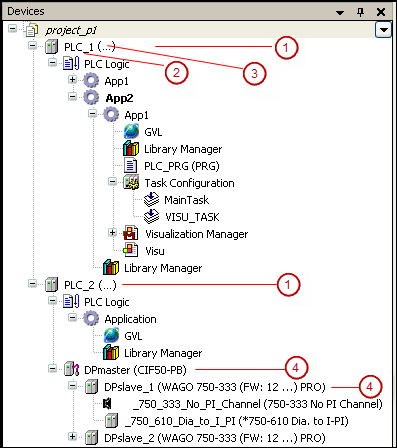 | (1) Programmable device (with application) (2) Symbolic device name (3) Device type, defined in the device description (4) Purely parameterizable device |
A device entry in the device tree consists of a symbol, the symbolic device name that is editable in the tree, and the device type (device name as defined in the device description).
All devices with bus cycle settings and tasks which are used for any number of bus cycle tasks are also marked with the  symbol. A tooltip is also displayed for tasks and devices with this symbol. For the tasks, the tooltip shows the devices used. For the devices, the tooltip shows the tasks.
You configure device communication, parameters, and IO mappings in the dialogs of the device editor. Open this editor by double-clicking the device object.
Rules and Procedures for Arranging and Configuring Objects in the Device Tree
Inserting objects
To insert a device object, click Add Device or Insert Device by right-clicking in the device tree. For other objects, click Add Object. CODESYS always provides the suitable objects at the currently selected position in the tree. Example: Modules for a PROFIBUS DP slave can be inserted only below a respective slave object, and applications inserted only below programmable devices. The selection of device objects also depends on which devices are installed in the device repository.
The following recommendations and rules apply for the names of the objects:
The size of 80 characters should not be exceeded. A compiler warning is generated for more than 80 characters.
Only alphanumeric characters and the underscore are permitted.
The first character must be a letter or an underscore.
You can only insert device objects on the level directly below the <project name> root node. If you select another object type, such as a text list, then CODESYS automatically inserts this into the POUs view (project-global pool).
Inserting applications
You can insert an Application object only below the PLC Logic node (a programmable device). All applications must be named uniquely for each device. Below each application, you can insert more objects that are required for programming, such as POUs, DUTs, GVLs, or visualizations.
Below each application, you need to insert a task configuration and configure the respective program calls (from application-specific POUs, or POU "instances" from the POUs view).
If multiple applications exist directly below a device, then you will need to define settings for the I/O processing of the device. This includes the variables of the application which CODESYS uses for communication with the target system. The settings are configured on the PLC Settings tab of the device editor.
Hierarchical layout of applications and scopes: You can add an application below another application. We name the resulting construct: "parent application" – "child application". In this case, the following applies: The child application can access objects in the parent application, but not the other direction. The reason for this is that a child application should always be removable or exchangeable without affecting the parent application.
NOTE
After the parent application has been changed, a child application is removed from the controller when an online change is performed.
Insert devices
CODESYS inserts a device object in the tree as a node. If nodes are defined in the device description, then they are inserted automatically. A subnode can also represent a programmable device. Order of device objects in the tree (from top to bottom): For each level, the programmable devices (PLC Logic) are listed first and then the other types in alphabetical order.
Update devices
A device which has been inserted into the device tree can be replaced by another version of the same device or by a device of another type (Update devices). A configuration tree below the device is available when possible.
Moving and deleting objects
You can use the standard commands Cut, Copy, Paste, and Delete on objects, or drag an object to another position. When you copy objects, the new object gets the same name with a consecutive number.
Network scan (of the current hardware)
By default, creating the PLC configuration in the device tree is supported by the device editors with scan functionality. The current hardware environment is scanned and the detected modules are displayed in a dialog. From there, you can save the required device directly to the device tree. See the Scan Devices command.
For more information, see: Mapping a Hardware Structure in the Device Tree
Device tree in online mode
In online mode, a symbol before a device entry indicates the device status.
 : The PLC is connected, the application is running, the device is in operation, and data is being exchanged. The Refresh I/Os in stop check box on the PLC Settings tab can be selected or cleared.
 : The PLC is connected and in STOP; and the Refresh I/Os in stop check box on the PLC Settings tab is cleared.
 : The device is not exchanging data; bus error, no configuration, or simulation mode.
 : The device is running in trial mode for 30 minutes. After this time has elapsed, the trial mode will expire and the fieldbus will terminate the data exchange.
 : The device is configured, but not fully operational. No data is exchanged. Example case: CANopen devices when booting and in preoperative mode.
 : Redundancy mode is active. The fieldbus master is not sending any data because another master is active.
 : The device description could not be found in the device repository.
 : The device itself is running, but a child device is not running or it has a diagnostic message. The child device is not visible due to a collapsed device tree.
 : Gray exclamation mark: A diagnosis was pending. However, the cause of the error no longer exists or has been resolved. This symbol can appear in connection with various other symbols in this list.
 : Red exclamation mark: The device is not running or a diagnosis is pending. The error cause still exists. This symbol can appear in connection with various other symbols in this list.
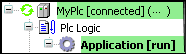
The names of all connected devices and applications are highlighted in green:
The names of devices that are running in simulation mode are displayed in italics:  .
.
Additional diagnostic information is located on the Status tab of the respective device editor.
Tip
If you log in while the device description on the target device is more recent than in the project, then a warning prompt opens with the possibility to cancel the process.
For more information, see: Command: Acknowledge Diagnosis, Acknowledge Diagnosis for Subtree and Downloading an Application to the PLC
Meaning of the colors of the POUs
The names of the POUs in the device tree are sometimes displayed in different colors.
Black: Default color; no specific meaning
Gray: Displayed after a code generation and indicates that the POU is not used in the project
Blue: Displayed after a code generation and when the project has already been downloaded one time. The POU has changed as compared to the POU on the controller and will be included with the next download.
Blue-green: The POU has the Exclude from build property set.
Device editor
You can configure the settings for communication between CODESYS and the target device on the tabs of the device editor. Double-click the device object in the device tree to open the editor.
The editor includes generic as well as specific tabs. Its title contains the device name.
For more information, see: Configuring Devices and I/O Mapping