Linking Your Own I/Os
With this functionality, local I/Os can be connected to a controller and used from the IEC application.
The UDSIoDrvExample.project example is included in the Extension Package Example. After the example package has been installed, you will find the project in the directory C:\Users\<user name>\CODESYS Examples\Extension Package Example\<version>\Files\ExternalIoDrv.
For more information, see the following: Example: Linking I/Os Created with a Device Description via UDS (Unix Domain Sockets).
Editing the device description
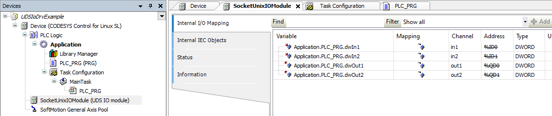
In the UDSIoDrvExample.project example, two inputs and outputs are created with the device description. The inputs and outputs are linked via a Unix Domain Socket.
To define your own inputs and outputs, the device description file SocketUnixIOTemplate.devdesc.xml must be modified. An XML parameter element must be defined for each of the inputs and outputs. The ParameterId must be unique here within the device description file. We recommend simply numbering in ascending order without gaps (example: 1000, 1001, 1002, etc.). Inputs should be numbered starting at of 1000, and outputs starting at 2000.
Note
After the device description has been modified, it must be reinstalled in the device repository so that it is available in the project.
<Parameter ParameterId="1000" type="std:DWORD">
   <Attributes channel="input"/>
   <Default/>
   <Name name="local:in1">/Namne>
</Parameter>
Name | Description |
|---|---|
ParameterId | Unique ID by which the input or output is called |
type | Definition of the width of the input or output. It is done by specifying an appropriately wide data type such as |
Attributes channel |
|
Name name | Name for the respective input or output |
Moreover, the device ID has to be assigned, which is defined in <DeviceIdentification>. The range 0x0001 8000 to 0x0001 80FF is provided for this purpose to avoid collisions with existing devices.
Important
The device description as well as the underlying I/O driver should not be instantiated multiple times under one PLC because the order of the modules is not fixed. This can lead to the I/O driver not being able to ensure the assignment.
Python example
In the Python example uds_io_driver.py, the outputs are received and the inputs of the device are written. Input parameters (IEC outputs) are passed as tuples of strings (paramType, paramValue) with the parameter ID of the device description as the index.
The driver can handle the data types USINT, UINT, UDINT, and ULINT. Other data types have to be cast to a suitable data type.
Example: ('2000': ('UDINT', '11'), '2001': ('UDINT', '22')}. The output parameters are in the same format.
Also for the peer, an "output"/output parameter is nevertheless an output value which is to be transported "outwards" by the IEC application (for example, written out to real GPIOs). The UDS_IODriver_0 class implemented in the example extends the ExternalFunctionBase class. The name of the class is derived from UDS_IODriver_ followed by the instance index in ascending order. The Call() function is required, which is called from the mechanism from IEC. The IEC outputs can now be evaluated here and IEC inputs can be transferred.
Usage of the interface only as a member of the Linux | Yes |
Process separation | Yes |