User Inputs in the CFC Editors
Configure
You can configure the appearance, behavior, and printing for the entire project in the CODESYS options in the CFC Editor category. For example, on the View tab, you can configure the color of the connecting lines depending on the data type.
Editing
User Input | Description |
|---|---|
Cursor symbol | Requirement: Pointer is selected in the Toolbox view. The symbol indicates that you can edit in the editor. Select elements or connections to move them or to execute commands. |
Cursor symbol | Requirement: An element is selected in the Toolbox view. Clicking in the editor inserts the selected element. You can also drag an element to the editor. |
Dragging a function block instance from the declaration to the editor | Requirement: A line is selected in the declaration of the CFC. The instance is inserted as a box with name, type, and all pins. |
Dragging a variable from the declaration to a box pin to the editor | The variable is inserted as an input or output with a connection to the box pin in focus. Hint: The cursor indicates when your focused location is valid for a variable.  |
Dragging a variable from the declaration part to the editor | Requirement: The respective element is selected in the declaration.
When a variable is dragged from the declaration part to an existing replaceable element, the existing element is replaced. |
Dragging a function block or POU to the editor from the Devices view, POUs view, or from the Library Manager | A box element with the corresponding type is inserted.
|
Resorting the order of inputs and outputs within a function block by means of Drag&Drop | Requirement: The text field of the input or output, which should be resorted to another location, is selected. |
Ctrl + click in the programing area | Requirement: An element is selected in the Toolbox view. As long as you hold down the Ctrl key, a selected element is created each time you click in the programming area. |
Ctrl+Right Arrow | Requirement: In the CFC program, exactly one output pin is selected for an element. The selection is moved so that the input pin at the end of the connecting line is selected. In the case of multiple pins, all are selected. 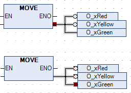 |
Ctrl+Left Arrow | Requirement: In the CFC program, exactly one input pin is selected for an element. The selection is moved so that the output pin at the beginning of the connecting line is selected. In the case of multiple pins, all are selected. Example: 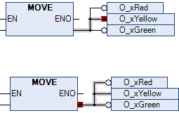 |


Connecting
You can insert connecting lines between element connections. Connecting lines are inserted by means of auto-routing so that connecting lines are automatically optimal and as short as possible. The connecting lines are checked for collisions.
User Input | Description |
|---|---|
Dragging a pin to another pin | A connecting line is inserted between the two element pins. |
Dragging a pin to a function block | Dropping can be done on a pin or on the text field of a pin. In the case of extendable operators (example: ADD), dropping can also be done within the box. The following behavior applies for this. If there are still unconnected input pins, then the top free pin is connected. If there are no more unconnected input pins, then a new pin is automatically inserted below. |
Command | Requirement: Multiple pins are selected. The pins are marked in red. |
Move an inserted element so that it touches the pin of another element. | Requirement: The Enable AutoConnect option is selected. The touching pins are connected automatically. |
 | The connection icon is located in the upper right corner of the editor. A green icon indicates collision-free connections. A red icon indicates collisions. Clicking the icon opens a menu with commands for collision processing, for example the Show Next Collision command. |
 | Requirement: A connection is selected and the Connection Mark command is executed. Instead of a long connecting line, a connection is represented by connection marks. |