Automatic Execution Order by Data Flow
The execution order in POUs is uniquely determined in text-based and network-based editors. In the CFC editor, however, you can position the elements freely, so the execution order is initially not unique. For this reason, CODESYS uses the data flow to determine the execution order and, in the case of multiple networks, by means of the topological position of the elements. The top elements and networks are sorted from top to bottom and left to right. In this way, the execution order is unique and makes sure that the POU is processed while optimized by time and by cycle.
You can temporarily display the current execution order in the chart. When you program networks with feedback, you can define an element as the starting point in the feedback loop.
You can also explicitly edit the processing order in a CFC object. To do this, switch the Auto Data Flow Mode property of the CFC object to Explicit Execution Order Mode. In this mode, you have the option of editing the execution order by means of menu commands.
Before CODESYS V3.5 SP15, you had to define the execution order explicitly for each POU. The was no mode switching.
Data flow
Data flow describes in chronological order which data should be written or read, how and when it should be done, and in which programming objects. A POU can process any number of data flows, which can also be executed independently of each other.
Displaying the execution order
By default, the execution order of a CFC object is determined automatically. The Auto Data Flow Mode property is selected for this. You can temporarily display the automatically determined execution order in the CFC editor.
Create a new project using the Standard Project template and specify the name
Minimalfor example.Extend the application with the function block
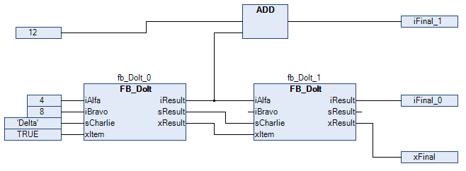
FB_DOItin the ST implementation language with inputs and outputs as follows.FUNCTION_BLOCK FB_DoIt VAR_INPUT iAlfa : INT; iBravo: INT; sCharlie : STRING := 'Charlie'; xItem : BOOL; END_VAR VAR_OUTPUT iResult : INT; sResult : STRING; xResult : BOOL; END_VAR VAR END_VAR iResult := iAlfa + iBravo; IF xItem = TRUE THEN xResult := TRUE; END_IFCreate the function block
ExecuteCFCin the CFC implementation language as follows.PROGRAM ExecuteCFC VAR fb_DoIt_0: FB_DoIt; fb_DoIt_1: FB_DoIt; iFinal_1: INT; iFinal_0: INT; xFinal: BOOL; END_VARRecently created programming objects in CFC have the Auto Data Flow Mode selected. The execution order of the programming object is optimally defined internally.
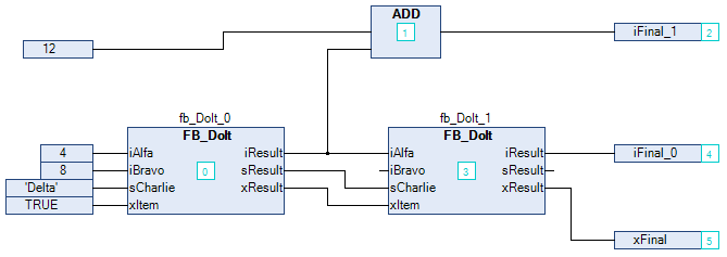
Click .
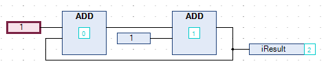
The execution order of the object is shown. The boxes and inputs are numbered accordingly and reflect the chronological processing sequence. The numbering is hidden as soon as you click again in the CFC editor.
Determining the execution order in feedback networks
Create a CFC program with feedback.
The POU
PrgPositiveFeedbackcounts.PROGRAM PrgPositiveFeedback VAR iResult: INT; END_VAR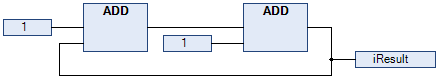
Select an element within the feedback.
The selected element is highlighted in red.
Click CFC → Execution Order → Set Start of Feedback.
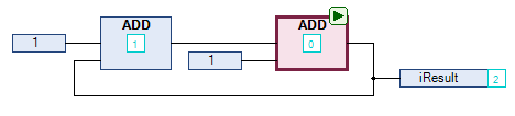
At runtime, this POU is processed first. The start POU of the feedback is defined and decorated with the
 symbol. The execution order is resorted and the selected element gets the number 0. (This is the lowest number of the feedback.)
Select the start POU again.
Click CFC → Execution Order → Set Start of Feedback.
The box is not selected as the start box.
The execution order is defined internally.
Click CFC → Execution Order → Display Execution Order.
The execution order by data flow is displayed.
Defining the execution order explicitly
You can change the automatically defined execution order of a CFC object explicitly when you select the Explicit Execution Order Mode option for the object.
In the Devices or POUs view, open the context menu of a CFC object and click Properties. In the Properties dialog, select the CFC Execution Order tab.
The Execution order list box displays the currently selected mode.
In the Execution order list box, select Explicit Execution Order Mode and click OK to confirm the dialog.
The "Explicit Execution Order Mode" is selected. The networks are numbered in the CFC editor, and the following commands are provided in the CFC → Execution Order menu for editing the execution order.
Open a CFC object.
Select a numbered element and click CFC → Execution Order → Send to Front.
The execution order is resorted and the selected element has the number 0.
Tip
The automatically defined execution order by data flow results in time- and cycle-optimized execution of the POU. You do not need any information about the internally managed execution order during the development process.
In Explicit Execution Order Mode, it is your responsibility to adapt the execution order and to assess the consequences and impacts. This is another reason why the execution order is always displayed.