Functions
CANopen Safety
CANopen Safety is released as a European standard (EN 50325-5). This means that data can be transmitted via CAN networks which meet the requirements for SIL3 applications. This safety-oriented data transmission can occur parallel to an existing CANopen data transmission. CODESYS CANopen Safety supports the safety demands according to SIL2.
In addition to the conventional CANopen services for data transmission such as SDO and PDO, a special service for this data transmission is defined for the safety extension with the SRDO service (safety related data object). Regarding configuration and type of communication, it is similar to a PDO, but additional properties are defined.
To use CANopen Safety, the CANopen Manager SIL2 is inserted in the device tree instead of the CANopen Manager. Both safe devices (yellow device icon) and unsafe devices (gray device icon) can be inserted below this manager. As a result, unsafe and safe CAN subscribers can be operated in parallel. The safe subscribers have safety-specific pages in addition to the usual configuration pages. The SRDOs (safe PDOs) as well as their CRCs can be configured in these. Besides the usual unsafe device instances, an additional instance with prefix "S_" is generated for each safety device (CANopen Manager and Slaves). This provides safety-specific diagnostic capabilities.
The use of the CANopen Manager SIL2 requires a SIL2 CODESYS Runtime with a specially adapted CAN mini-driver and a CODESYS SIL2 plug-in. The required libraries and devices are already included in the standard installation.
Redundancy
With the CODESYS Redundancy Toolkit, two CANopen Managers can be used in a redundancy configuration. In this case, the passive controller monitors the activities of the active controller and takes over the active role when a communications failure is detected. The monitoring is done by means of two parallel mechanisms:
Monitoring of the CODESYS Redundancy Toolkit (mostly via Ethernet)
Monitoring of the CANopen Manager heartbeat. The desired timeout is set in the configurator of the CANopen Manager.
Tip
The "CODESYS Redundancy Toolkit" add-on is required for the "Redundancy" function. Furthermore, you need to configure the redundancy in the device tree.
For more information, see: CODESYS Redundancy
Reconfiguration – CANopen Manager
With the "Reconfiguration" function, you can dynamically adapt a CAN bus configuration at application runtime which was initially downloaded to the controller.
With the function block DED.Reconfigure, which is available when the generic device diagnosis is enabled (PLC Settings:), you can execute the following actions at runtime.
Activation and deactivation of individual devices
Activation and deactivation of an entire bus strand
Tip
For more information about reconfiguration on the CANbus level, see the chapter Reconfiguration – CANbus.
Command: Scan for Devices
Dialog: Scan Devices
Device name, Device type, Address, Station name, etc. | Data about the scanned device depending on network type. When you change a value in the list of scanned devices, the value is displayed in italics. This indicates that the new value has been changed in the editor in CODESYS, but not in the device. When you download the value to the device, it is displayed normally. Values which indicate differences between the project and the scanned device are displayed in orange. If multiple device descriptions are available for the scanned device, then the name is displayed in bold. The selection of the matching device description is resolved differently for different fieldbuses. For more detailed information, see the corresponding fieldbus chapters. If a device description cannot be found, then the following message is shown: "Attention! The device was not found in the repository." Depending on the bus system, additional information is displayed, such as vendor number and product number. The device cannot be inserted into the project without the installed device description. |
Show differences to project |
|
Scan for Devices | Starts a new search. |
Copy All Devices to Project | The device which is selected in the table is inserted into the device tree in the project. If nothing is selected, then all scanned devices are shown. |


Important
If you use Copy All Devices to Project to insert devices, which are available in the device tree, to the device tree, then the following should be noted: The data of the Process Data and <...> I/O Mapping tabs of the existing devices may be overwritten with the data of the recently inserted devices.
This part of the dialog is visible only when you select the Show differences to project option. Differences between the scanned and configured devices are color-coded. Devices displayed in green are identical on both sides. Devices displayed in red are available only in the view of the scanned or configured devices. | |
 | If you have selected a device in both views, then the scanned devices are inserted above the selected configured device. |
 | If you have selected a device in both views, then the scanned devices are inserted below the selected configured device. |
 | If you have selected a device in both views, then the configured devices are replaced by the selected scanned device. |
 | All scanned devices are copied to the project. |
 | Deletes the selected configured device. |
Behavior of the bus cycle for CANopenManager
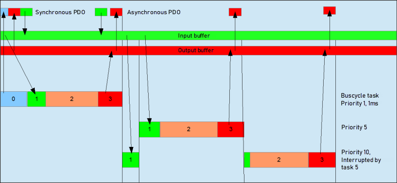
0: Sending/receiving of synchronous PDOs
1: Receiving of asynchronous PDOs
2: IEC task
3: Writing the outputs in the output buffer
For more information, see: task configuration