CANbus Diagnosis
Diagnosis of Hardware Failures
Most CAN problems are traced back to incorrect wiring or faulty CAN devices. Potential errors include the following:
Missing or incorrectly dimensioned terminal resistors
The bus has to be terminated exactly with a 120 Ω terminal resistance at the beginning and at the end.
Different baud rates
All subscribers have to use the same baud rate.
Short circuit between CANLow, CANHigh, CANGround, V+
CANLow and CANHigh interchanged
Different lengths of CANHigh and CANLow
CANHigh and CANLow are not a twisted pair. As a result, signals can be interrupted more easily.
Different grounding sources for CANGround
Two-sided grounding of the CAN bus cable
When both ends of the shielding of the CAN bus cable are grounded, grounding loops can form which can cause interruptions.
Bus cable too long
The maximum bus length depends on the set baud rate (see table).
Bit Rate | Cable Length |
|---|---|
10 kbps | 6.7 km |
20 kbps | 3.3 km |
50 kbps | 1.0 km |
125 kbps | 500 m |
250 kbps | 250 m |
500 kbps | 125 m |
1 Mbps | 25 m |
Detecting hardware failures
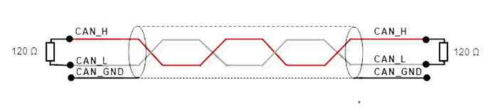
The terminal resistance is used to adapt the impedance of a node to the impedance of the used transmission cable. When there is a mismatch of the impedance, the transmitted signal is not completely absorbed by the load and part of it is reflected back into the transmission cable. If the impedances of source, transmission cable, and load are the same, then these reflections are eliminated. In this test, the serial resistance of the CAN data pair cables and the connected terminal resistors are measured.
Switch off the power supply of all CAN nodes.
Measure the resistance between CAN_H and CAN_L in the middle and at the end of the network.
The measured value should be between 50 Ω and 70 Ω. The value should be the same at all locations in the network.
If the value is less than 50 Ω, then make sure of the following:
There is no short circuit between the CAN_H and CAN_L cables.
No more than two terminal resistors exist.
The nodes do not have defective transceivers.
If the value is greater than 70 Ω, then make sure of the following:
No open circuit exists in the wiring of the CAN_H and CAN_L cables.
The bus system has two terminal resistors, each 120 Ω – one at each end.

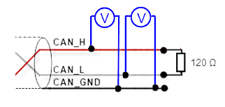
Every node contains a CAN transceiver which sends difference signals. When the network communication is idle, the voltages CAN_H and CAN_L are approximately 2.5 V. Faulty transceivers can cause the open-circuit voltages to vary and disrupt network communication.
Switch off the power supply of all CAN nodes.
Stop all network communication.
Measure the direct current between CAN_H and GND.
The measured value should be between 2.0 V and 4.0 V. If it is less than 2.0 V or greater than 4.0 V, then it is possible that one or more nodes have a faulty transceiver.
At a voltage less than 2.0 V, you need to check the CAN_H and CAN_L cables for continuity.
At a voltage greater than 4.0 V, you need to check for overvoltage.
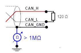
The shielding of the CAN network may be grounded at only one location. This test indicates whether or not the shielding is grounded at multiple locations.
Separate the shield from the ground.
Measure the direct current resistance between the shield and the ground.
Connect the shield to the ground.
The resistance should be greater than 1 MΩ. If it is lower, then you need to search for an additional grounding of the shield.
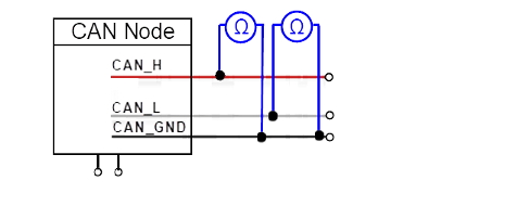
CAN transceivers have a circuit which controls CAN_H and another circuit that controls CAN_L. Experience has shown that electrical damage to one or both circuits can increase the leakage current in these circuits.
Use a resistance measuring instrument to measure the leakage current.
Separate the node from the network. Leave the node without any current.
Measure the direct current resistance between CAN_H and CAN_GND.
Measure the direct current resistance between CAN_L and CAN_GND.
Normally the resistance should be between 1 MΩ and 4 MΩ or higher. If it is lower than this range, then the CAN transceiver is probably defective.
Error Handling of a CAN Controller
Error handling is integrated into the CAN protocol and is extremely significant for the performance of a CAN system. Error handling aims at detecting errors in CAN messages so that the sender can resend a failed message. Every CAN controller tries to detect errors within a message. When an error is found, the detecting node sends an error flag and therefore disrupts the bus traffic. The other nodes will detect the error which was caused by the error flag (if they have not already detected the original error). They will take appropriate action and reject the current message.
These counters and also the bus state often provide initial insights into the cause of the error when diagnosing CAN errors. This information can be read in CODESYS by means of the user interface as well as the application.