Device Diagnosis Generator
The device diagnosis module is a standard component of the Application Composer, which is included in the library AC_DeviceDiagnosis. The module is a toplevel module and can be added to the module tree by the command Add toplevel module instance.
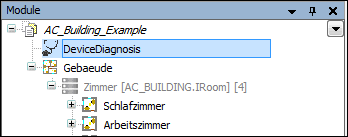
With the help of the device diagnosis module, a visualization page is created, based on the existing device configuration, which depicts the PLC and the connected fieldbus devices in a tree structure. In this tree structure, the state of each component is displayed. If necessary, detailed information can be called up or the operating mode of single components changed.
Requirements
The displayed diagnosis details come from the CAA-Device-Diagnose-FBs (device-FBs) which were created by the devices. To generate these components, the option Activate diagnosis for devices has to be set in the PLC settings. These FBs deliver not only the normal status information which is displayed in the (above) overview, but also detailed information, which is shown in an additional display. If the option Activate diagnosis for devices has not been set before generation, the generation process is aborted and the option is set automatically, so that the next generation run creates the desired visualization.
To generate this visualization page, the device diagnosis generator must be activated in the Generator configuration.
Device diagnosis in online mode
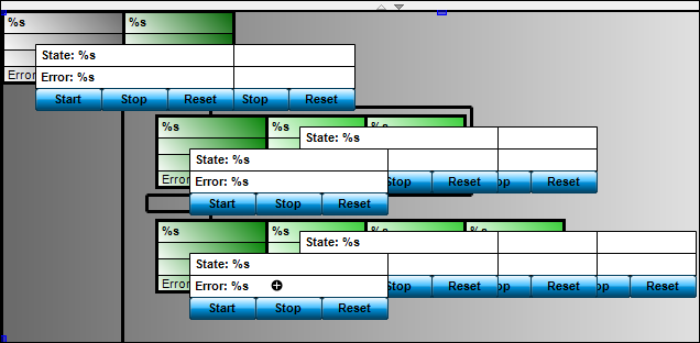
In online-mode, the name of the device, the status and the error code are shown.
The status of the devices is shown in a color scheme:
Green: The device has the status "Running"
Red: The device does not have the status "Running"
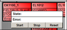
Clicking the device opens a window in which the device can be halted, (Stop), reset (Reset) or started (Start). When the dialog is opened for the first time, all functions are shown. Functions which are not supported by the hardware will be faded out upon first activation.