Binary Circuits in Ladder Diagram
Sample selection of POUs in the ladder diagram
LD block: FB_AssignToLamp.fb.ld
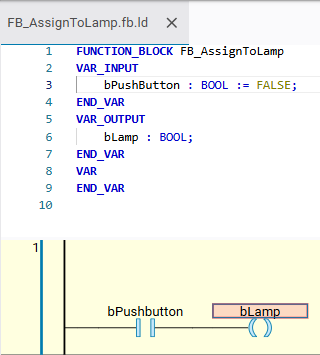
Equivalent in ST:
FUNCTION_BLOCK FB_AssignToLamp
VAR_INPUT
    bPushButton : BOOL := FALSE;
END_VAR
VAR_OUTPUT
    bLamp : BOOL;
END_VAR
VAR
END_VAR
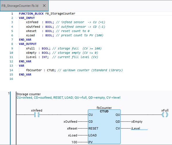
bLamp := bPushButton;FB_StorageCounterThe counter block FB_StorageCounter encapsulates a CTUD counter (preselection: PV= 100).
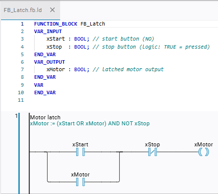
FB_LatchxMotor := (xStart OR xMotor) AND NOT xStop
The second branch line of the ParallelClosed branch reads back its own output xMotor (self-holding). xStop is in series as an opener.
xStartbrieflyTRUE→xMotorstays on (holds itself)xStopTRUE→xMotorshuts down.
Network
1:iSum := iValue1 + iValue2about aADD-Operator block.Network
2:xGreater := (iValue1 > iValue2)about aGT-Operator Block.
Both operator blocks have the EN enable input and the ENO enable output. Inputs are iValue1 and iValue2. Outputs are iSum and xGreater
PROGRAM PRG_CompareArithmetic
VAR
    iValue1  : INT := 10; // first operand
    iValue2 : INT := 5;  // second operand
    iSum     : INT;       // result iValue1 + iValue2
    xGreater : BOOL;      // TRUE if iValue1 > iValue2
END_VAR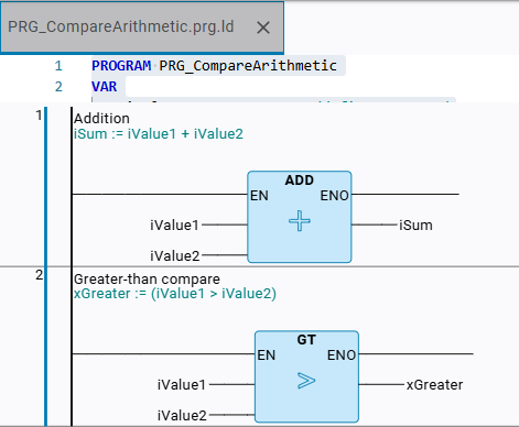
PRG_SetResetNetwork
1:xSet→ Set coil (S) onxLatch(Modifier.Storage = 1).Network
2:xReset→ Reset coil (R) toxLatch(Modifier.Storage = 2).
xLatch remains after xSet saves TRUE and is reset by xReset.
FUNCTION_BLOCK FB_Latch
VAR_INPUT
    xStart : BOOL; // start button (NO)
    xStop  : BOOL; // stop button (logic: TRUE = pressed)
END_VAR
VAR_OUTPUT
    xMotor : BOOL; // latched motor output
END_VAR
VAR
END_VAR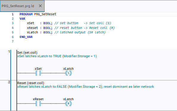
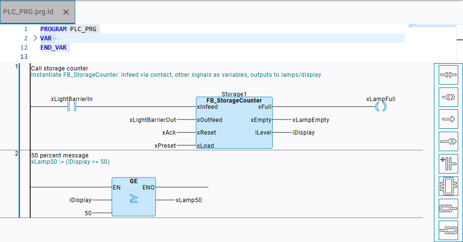
PLC_PRGNetwork
1:Instantiates
Storage1 : FB_StorageCounterand wires the signal inputs (xLightBarrierIn,xLightBarrierOut,xAck,xPreset) to the outputs for signal lamps (xLampFull,xLampEmpty) and for the display (iDisplay).Network
2:xLamp50 := (iDisplay >= 50)via a GE comparator.
PROGRAM PLC_PRG
VAR
    Storage1   : FB_StorageCounter; // counter instance
    xLightBarrierIn  : BOOL; // infeed light barrier  -> xInfeed
    xLightBarrierOut : BOOL; // outfeed light barrier -> xOutfeed
    xAck       : BOOL; // acknowledge / reset   -> xReset
    xPreset    : BOOL; // preset to 100         -> xLoad
    xLampFull  : BOOL; // "storage full" lamp
    xLampEmpty : BOOL; // "storage empty" lamp
    xLamp50    : BOOL; // ">= 50% full" lamp
    iDisplay   : INT;  // stock display
END_VAR