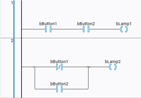
Creating a POU in LD
When you create a POU, you decide which implementation language you want to use for programming. A block in a ladder diagram can consist of one or more networks which are processed sequentially from top to bottom within a task cycle. The order can be controlled by jumps.
Right-click the application. In the menu, click Add Item and select the Function Block command.
The Add Function Block dialog will open.
Configure the new function block.
Choose a name.
FB_CounterSelect Ladder Diagram (LD) as the implementation language.
Click Create to close the dialog.
A new file named
FB_Counter.fb.ldwill be created in the navigator.fbstands for function block.ldstands for ladder diagram.The function block file will be displayed in the editor area of the function block. The declaration is displayed in the upper area, and the graphical implementation is displayed in the lower area. The element bar on the right will provide the elements for the ladder diagram. Because this is a new function block, the declaration and implementation are still empty.
In the element bar, select the
 symbol. Hold the left mouse button pressed down.
The Network element will be selected. The insert position (rectangle) for the network will be displayed in the editor.
Drag the element to the insert position.
The mouse pointer will show a plus sign.
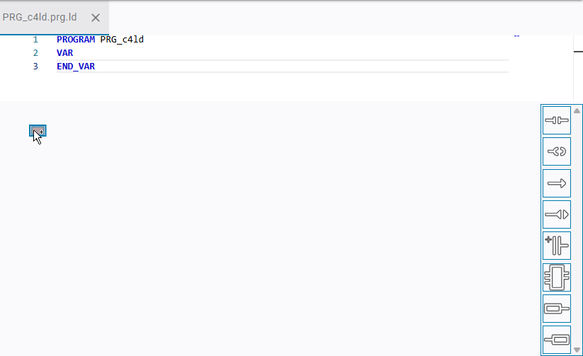
Release the left mouse button.
Network
1will be inserted.In the element bar, click the
symbol.Drag or click
You can drag an element from the element bar into the editor.
Alternatively, you could also click the desired element and then release the left mouse button. Then click one of the insert positions displayed in the editor.
The insert positions will be shown.
Click the lower insert position.
Network
2will be inserted.Program the desired logic.
Sample circuit