Setting Up the Monitoring of I/O Exchange and Device State
Monitoring the ModbusTCPClientSideExample project
In the
ModbusTCPClientSideExampleproject, open thePLC_PRG.prg.stprogram.Declare two variables named
readValueandwriteValueof typeWORD.Define a variable
maxValueof typeWORDwith the value100.Insert the following code into your implementation:
IF writeValue > maxValue THEN
   writeValue := 0;
END_IF
IF readValue = writeValue THEN
   writeValue := writeValue + 1;
END_IF
Note
As soon as the Modbus communication is established, this code will continuously increment
readValueandwriteValueuntil the limit is reached.Open the editor of the
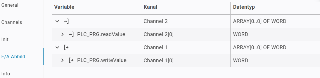
Modbus_TCP_Serverdevice and switch to the I/O Mapping tab.Expand the entries for
Channel 1andChannel 2.Map
PLC_PRG.readValueto theChannel 2[0]entry. The variable receives the value read by the request later.Map
PLC_PRG.writeValueto theChannel 1[0]entry. The variable provides the value to write.The result looks like this:
Switch back to
PLC_PRG.prg.stof theModbusTCPClientSideExampleproject.Declare a variable
serverComStateof typeIoDrvModbusTCP.ModbusTCPComState.Declare a variable
serverErrorCodeof typeIoDrvModbusTCP.MB_ErrorCodes.Add the following code to your implementation and adjust the server name to match the name used under Devices. In this sample project, the name is
Modbus_TCP_Server.serverComState := Modbus_TCP_Server.ComState; serverErrorCode := Modbus_TCP_Server.byModbusError;
This will allow you to monitor the communication state and the current error code by using the outputs of the device’s function block.
Monitoring the ModbusTCPServerSideExample project
In the
ModbusTCPServerSideExampleproject, open thePLC_PRG.prg.stprogram.Declare two variables named
registerValueandtempValueof typeWORD.Insert the following code into your implementation:
tempValue := registerValue;
Open the editor of the
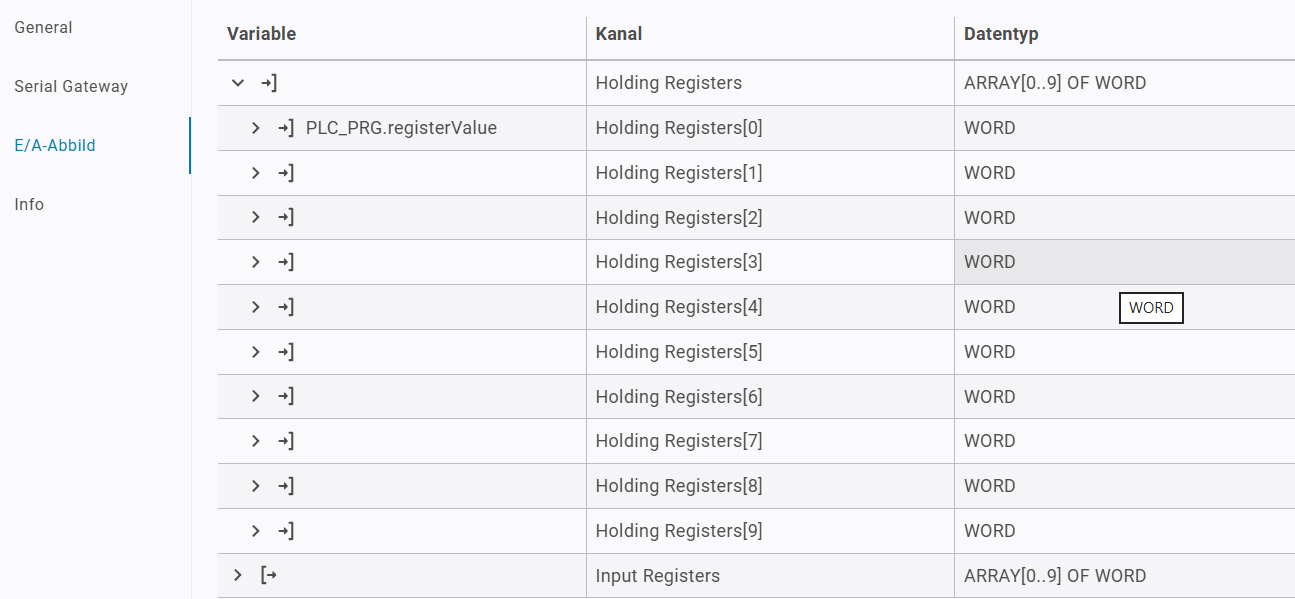
ModbusTCP_Server_Devicedevice and switch to the I/O Mapping tab.Expand the entry for Holding Registers.
Map
PLC_PRG.registerValueto theHolding Registers[0]entry. The variable contains the value of the register.The result looks like this:
Switch back to
PLC_PRG.prg.stof theModbusTCPServerSideExampleproject.Declare a variable
serverDeviceClientConnectionsof typeUINT.Declare a variable
serverDeviceErrorCodeof typeUINT.Insert the following code into your implementation:
serverDeviceClientConnections := ModbusTCP_Server_Device.uiClientConnections;
serverDeviceErrorCode := ModbusTCP_Server_Device.ErrorCode;
This code will allow you to monitor the current number of clients connected to this server and the current error code of the server.
Note
Now the setup for the Modbus communication and the monitoring of the devices are complete.