Kin_HGantry2 (FB)
- FUNCTION_BLOCK Kin_HGantry2 IMPLEMENTS ISMPositionKinematics_Offset,
ISMPositionKinematicsInternal, ISMKinematicWithInfo2
Transformation FB for a 2-axis H gantry.
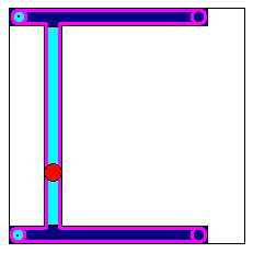
The kinematics configuration is similar to that described in Kin_Gantry2. However, the drives are mounted stationary. They move the y-axis rail and slider by means of a drive belt on the perimeter of the frame. (see picture aside; belt in pink).
Machine coordinate system (MCS) |
|
|---|---|
Origin |
Location of the TCP when the position values of both axes are 0. |
X |
The X axis is defined so that a positive velocity on the first axis (a0) together with a negative velocity of the same amount on the second axis (a1), leads to a movement purely along the X axis in positive direction. |
Y |
The Y axis is defined so that negative velocities of the same amount on both axes, lead to a movement purely along the Y axis in positive direction. |
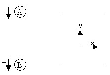
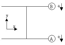
The transformation is adequate for the following axes configurations (other configurations can be reached by interchanging A and B):
The orientation of the tool coordinate system equals the one of the machine coordinate system.
The single axes values have the following interpretation:
a0 |
position of the 1st axis of the machine (A) |
a1 |
position of the 2nd axis of the machine (B) |
- Attributes:
sm_kin_libdoc
Properties:
Methods:
Structure: