Gantry System with Tool Offset
If the axis of the tool has an offset and does not coincide with the Z-axis of the gantry system, then the contact point of the tool does not agree with the X/Y/Z-position of the gantry system. If the Z axis cannot be rotated, then the resulting offset of the X and Y coordinates is constant and can be used directly for the standard gantry transformation.
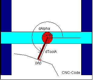
If the tool is rotated by the C axis (about Z), then the offset is not constant, but depends on the position of the C axis. In this case, one of two POUs can be selected, depending on the form of the tool:
SMC_TRAFO_Gantry2Tool1andSMC_TRAFOF_Gantry2Tool1The tool points along the X axis rotated by
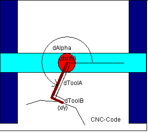
dAlphaand has a length ofdToolA.SMC_TRAFO_Gantry2Tool2andSMC_TRAFOF_Gantry2Tool2The tool is partially in the direction of the X axis rotated by
dAlpha(length:dToolA) and partially in the direction of the rotated Y axis (length:dToolB).
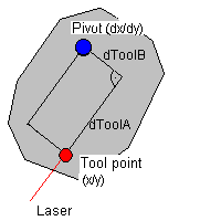
In the figure of the following example, the laser is attached with an offset in both the X direction and Y direction.
Instead of executing this one-dimensional transformation, the path can also be modulated with a tool offset. At this time, the tool approaches a straight line. The SMC_ToolCorr or SMC_ToolRadiusCorr function blocks are used for this. The difference between these two methods is the velocity of the tool point. If the modulation is used from SMC_ToolCorr, then the velocity of the rotational point is controlled according to the presets in the CNC program (F, E). The velocity of the tool point can fluctuate. If the one-dimensional transformation is used, then the velocity of the tool point is determined by the CNC program.
To calculate the orientation of the tool, the SMC_CalcDirectionFromVector POU is used.