Configuring PiFace Digital
Controlling PiFace Digital I/O hardware
Requirement: The PiFace Digital expansion hardware is connected.
The PiFace.project project contains an application which controls a Raspberry PiFace Digital I/O hardware with 8 digital inputs and outputs.
Open the
PiFace.projectproject and update it.In the device tree, double-click
Device.The device editor opens.
On the Communication Settings tab, click Scan Network.
If your Raspberry Pi and the development system are on the same network, then your Raspberry Pi is displayed for selection.
Select it and click .
The application is downloaded to your Raspberry Pi.
Start the program (press the F5 key).
When you press the S1 button, the K0 relay output is switched with a time delay of one second. When you press the S2 button, K1 is switched immediately. K1 is held by half a second after S2 is released.
Also note that you can use multiple instances (hardware address changeable via jumper JP1, JP2) by adjusting the device parameter at the PiFace device in the device tree accordingly.
The Raspberry SPI_PiFace library, which enables the connection, is available to them as source code. It can be used as an example for other connections.
The Raspberry Pi Peripherals library is the basis for communication via SPI. Their interfaces are documented both in the help and in the Library Manager.
Controlling the PiFace Digital module via I/O drivers
Requirement: The PiFace Digital expansion hardware is connected.
The PiFaceIoDrv.project project contains an application which controls a Raspberry PiFace Digital I/O hardware with 8 digital inputs and outputs. But an I/O driver is used instead of an implicit FB instance. The I/O driver implements the exchange of inputs and outputs in the usual way for controllers by means of the process image.
The IoDrvPiFace library contains the I/O driver as source code.
Controlling and operating with the PiFace Control and Display module
Requirement: The PiFace Control and Display expansion hardware is connected.
The PiFaceDisplayAndControl.project project contains an application which controls a two-line text display in addition to the Raspberry PiFace Digital I/O hardware with 8 digital inputs and outputs in order to configure application parameters.
Tip
You can reach the PiFace Control and Display board via SPI port 1 /dev/spidev0.1 which is configured in the SPI Master.
When the device is added to the device tree, an FB instance is created which provides various methods and properties for controlling the device. Moreover, the state of the buttons is returned. Bits 0 to 7 of the bySwitches output stand for the following buttons:
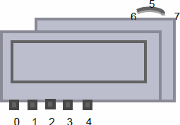
In the sample project the PiFace_Control_Display FB is passed to an instance of the ParamListPiFace FB which implements a parameter editor. In its view mode, you can scroll through the parameter list by means of the navigation button (6/7). By pressing the navigation button (5), you can see the parameter of the first line in detail. You exit the detailed view by pressing button 4. Press 5 again to enter the editing mode. There you can change the value in the permitted range with the buttons 0 and 1. With button 2, the value is stored. Press button 4 to exit the editing mode.